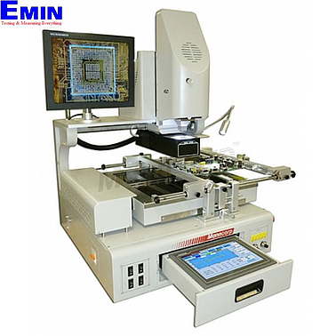
Manncorp BR790-HD SMT/BGA Rework Station
Manufacturer: MANNCORP Model: BR790-HD - Request a Quotation

- Request a Quotation
- Contact
See more: Equipment Calibration-Inspection & Repair Service
Call for the best priceHanoi city: (024) 35.381.269
Danang city: (023) 63.747.711
Bac Ninh city: (0222)730.39.68
HCM city: (028) 38.119.636
Discontinue
Option:
NOZ7x7: Topside nozzle 7 mm x 7mm for BR series
NOZ8x8: Topside nozzle 8 mm x 8 mm for BR series
NOZ9x9: Topside nozzle 9 mm x 9 mm for BR series
NOZ12x12: Topside nozzle 12 mm x 12 mm for BR series
NOZ15x15 :Topside nozzle 15 mm x 15 mm for BR series
NOZ18x18 :Topside nozzle 18 mm x 18 mm for BR series
NOZ20x20 :Topside nozzle 20 mm x 20 mm for BR series
NOZ21x21 :Topside nozzle 21 mm x 21 mm for BR series
NOZ24x24 :Topside nozzle 24 mm x 24 mm for BR series
Quick Overview
High-Definition, Auto-X-Y Split-Vision Alignment for Automatic Removal, Placement, and Soldering of BGAs, CSPs, QFPs, and Other SMDs
Split-vision optics with a 1.3 million pixel, high-definition video camera and five separate thermocouple inputs make the Manncorp BR790-HD the ultimate solution for safe, repeatable removal, alignment, placement, and soldering of BGAs, CSPs, ultra-fine-pitch QFPs and other delicate, heat-sensitive, and expensive SMDs. Motorized X- and Y-axis control of the split-vision optics, ultra-sensitive Z-axis height-sensing controlled by optoelectronic switching, and a 6-zone rapid-IR underheater also contribute to performance that makes the BR790-HD the most advanced rework system Manncorp has ever offered.
Details

Easily Adjustable PCB Holder Accepts Boards Up To 550 mm x 500 mm
The BR790-HD unique board holding system accommodates virtually any surface mount or mixed technology PCB assembly up to 550 mm x 500 mm (21.6" x 19.7"). A wide range of X- and Y-axis adjustability, universal PCB support rails, and a moveable 6-zone, high-efficiency, rapid IR underheater ensure that any application set-up can be optimized to take full advantage of all the BR790-HD advanced features.

Unique PCB Clamping and Support System Adjusts in Seconds
Unlike most PCB holders with adjustable edge rails, boards placed onto the BR790-HD support rails are locked in place by a series of independently adjustable clamps that can be positioned at any desired location along the rail. With the flip of a lever, the clamps lower from their raised position (shown at left) to the locked position (shown at right). With the board held securely, the rework site can easily be positioned between the top and bottom heaters, and the bottom heater raised to the PCB, without any danger of the PCB falling off the rails.

Innovative Laser Guide for Easy Alignment of Component Over Bottom Side Heater
Proper setup of the BR790-HD calls for alignment of the bottom heater, the component, and the top heater in the Z axis. Positioning the board in the PCB holder so that the component on the top side is positioned directly over the bottom heater nozzle is facilitated with a handy laser pointer that is mounted to the base structure and is targeted at the virtual center of the bottom heater. Positioning the component on the PCB below the laser spot ensures that the bottom heater, component, and upper heater are virtually aligned and reduces setup time.

X, Y, and Theta Axes Micrometers for Alignment of Component Leads to PCB Pads
Ultra-fine micrometers on the PCB holder for X- and Y- axes, and an additional one on the pick-up head for the theta axis, allow fast, easy, and precise alignment of the component leads to the PCB pads. Alignment is performed with the aid of ultra-high-resolution images of the board and the component, superimposed by the High-Definition Split-Vision Optics and projected onto the large 15" LCD display.

Auto-Pickup of SMDs from the Component Presentation Nest Protects
In preparation for alignment and soldering, new or re-balled SMDs are gently placed in the corner of the Component Presentation Nest which is attached to the Split-Vision Optics. When the alignment function is initiated, the Split-Vision Optics X-Y drive motors automatically position the component directly under the pickup head and soldering nozzle. The pickup head and soldering nozzle are then automatically lowered and the component is picked up. With the component suspended on the vacuum nozzle, the Split-Vision Optics are then automatically positioned between the component and the PCB so that the bottom of the component and the pads on the PCB are simultaneously displayed on the BR790-HD full color 15" LCD display. These features protect components from damage due to mishandling and dramatically reduce cycle times by eliminating the need for operators to position the Split-Vision Optics.

High-Definition (1.3 Million Pixels) Split-Vision Optics for Precise Alignment
High Definition Split-Vision Optics, with electronic zoom and focus, and high-brightness adjustable LED lighting provide high-contrast superimposed images of the component leads (as it is being held on the placement head) and the pads on the PCB. The operator views this image on the BR790-HD full color 15" LCD display and if the component leads are misaligned with the pads on the PCB (as shown at left)...

...the X-, Y-, and Theta axes micrometer adjustments can then be used to align the component and board (as shown at left). Once the component leads and pads are aligned, precise placement is ensured.
 Touch Screen Control and Five Thermocouple Inputs for Precise Profiling
Programming and setup of the BR790-HD are performed through the use of a convenient LCD touch screen controller and touch pen that, when not being used, slide into the system base for safe storage. Five separate thermocouple inputs allow real-time monitoring of actual temperatures at a variety of critical locations on the PCB and components. Screen captures of actual process profiles can then be saved to a separate memory device connected to the built-in USB port on the side of the controller. Separate controls for the split-vision optics upper and lower high-brightness LED lighting provide maximum clarity and contrast between the superimposed images of the component leads and PCB pads on the BR790-HD full color 15" LCD display.
 Large 6-Zone Rapid IR Underheater Prevents Thermal Stress & Improves Efficiency
The BR790-HD large PCB capacity is complemented by a 6-zone "Rapid IR" underheater with a generous 470 mm x 350 mm heating area to evenly and efficiently heat the bottom of the board. Not only does "Rapid IR" prevent board warpage and stress on components and solder joints adjacent to the rework site; it also reduces overall cycle times and maximum temperature exposure. Programmable power settings are capable of supplying up to 3600 watts of power and, for energy savings, separate control switches allow activation or deactivation of zones relative to PCB size. Tinted glass shields over the heating elements dissipate heat rapidly and isolate the heater compartment.

One-Touch Rework Functions and Parameter Adjustment On-the-Fly
The BR790-HD user interface features password protected user privileges that separate operator and administrative/programming functions. Operator controls allow one-touch functionality for desoldering operations with automatic placement and soldering also taking place at the touch of a button. When creating profiles, the ability to edit parameters from the same screen where the real-time temperature profile is displayed provides almost instantaneous feedback and reduces setup time.
 BR790-HD Rework System Features
Programmable Heating Rate, Target Temperature, and Dwell Time
Sets of profile parameters for both leaded and lead-free solders can be divided into as many as eight individual segments for both the top and bottom heaters, each with its own heating rate, target temperature, and dwell time at the targeted temperature. Temperature and power settings for the IR underheater and the duration of the cooling fan operation are also saved as part of the parameter set.

Real-Time Data Recording and Profile Analysis
The five separate thermocouple inputs allow real-time monitoring of temperatures at the desired locations on the component or PCB. Collected data can be analyzed to ensure consistency with solder and/or component manufacturer recommendations and can also be captured in bitmap format and written to a memory device connected to the BR790-HD standard USB port.

Full Set of Vacuum Nozzles Included for Automatic Pick-Up and Placement of SMDs
The BR790-HD comes with a complete set of vacuum nozzles to handle components from 3 mm x 3 mm up to 80 mm x 80 mm and a maximum weight of 70 grams. High temperature silicone vacuum tips and adapter sleeves attach to the standard vacuum nozzles to increase contact area and pick-up force.

Bottom Heater Nozzles Included To Handle Most All BGA and CSP Applications
The BR790-HD is also shipped with 36 mm x 36 mm and 58 mm x 58 mm bottom heater nozzles to accommodate 95% of all rework applications involving removal and resoldering of BGAs, CSPs, and other devices that require bottom heating. Bottom heater nozzles can also be supplied in custom sizes for applications that require confinement of heat to a smaller area.

Wide Variety of Upper Heater Nozzles To Solder or Desolder Virtually Any SMD
Nozzles for the upper heater are ordered based on the user needs and are available in virtually any size to direct heat to the top surface and perimeter leads of a surface mounted device. A full listing of standard nozzles and pricing is available in the BR790-HD Options/Accessories area, and custom sizes are also available upon special request. Upper Heater Nozzles are held in place in a magnetic collar that allows quick, “tool-less” changeover in just a few seconds.
BR790-HD - Specifications
| PCB Specifications | |
|---|---|
| PCB Size (Minimum) | 20 mm x 20 mm (0.79" x 0.79") |
| PCB Size (Maximum Allowable) | 500 mm x 550 mm (19.7" x 21.6") |
| PCB Size (Recommended Max.) | 470 mm x 350 mm (18.5" x 13.8") |
| PCB Thickness | 0.5 mm - 6 mm (0.019" - 0.24") |
| Component Specifications | |
| Component Size | 3 mm x 3 mm to 80 mm x 80 mm (0.12" x 0.12" to 3.15" x 3.15") |
| Minimum BGA Ball Pitch | 0.3 mm (0.012") |
| Placement Precision | ±0.02 mm (0.0008") |
| Heating System | |
| IR Under-Heater | Max. Heat Area - 470 mm x 350 mm (3600 W) |
| Component Heater (Top Side) | Hot Air (1200 W) |
| Component Heater (Bott. Side) | Hot Air (800 W) |
| Temperature Control | K-Type Thermocouple; Closed Loop PID |
| Utility Specifications / Facility Requirements | |
| Main Power Source | 220 V ± 10%/ Single Phase / 50/60 Hz |
| Total Power Consumption | 5.6 KW Max. (25 A) |
| Machine Dimensions | 850 mm L x 750 mm W x 630 mm H (33.5" L x 29.5" W x 24.8" H) |
| Net Weight | Approx. 70 Kg (154lbs.) |
- Quality Engagement
- Easy change and return
- Delivery Avaliable
- Favorable payment