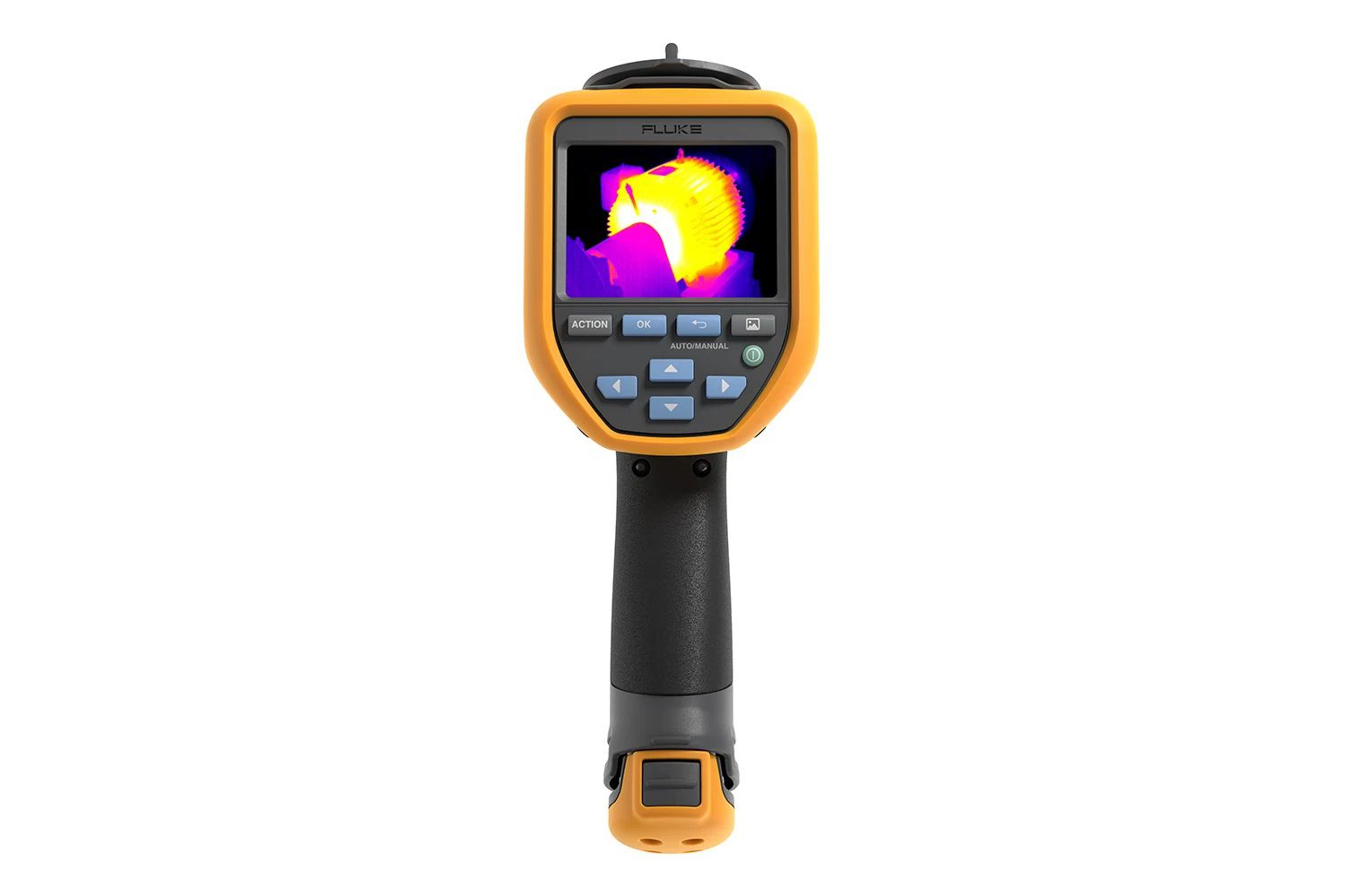
In industrial plant operations and energy infrastructure, issues such as overload, short circuits, or performance degradation frequently stem from increased contact resistance, material wear, or electromechanical anomalies. The application of thermal imaging cameras allows for non-contact infrared radiation measurement, converting thermal energy into an intuitive color map to detect anomalies early while the system is operating under load.
Hotspot Detection Mechanism in Switchboards, Power Lines, Solar Arrays, and Auxiliary Systems
According to Joule's law (P=I^2 R), any location with increased resistance or impeded current flow generates significant heat, forming a hotspot before physical damage occurs:
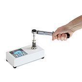
Distribution Switchboards and Switchgear: Abnormal temperatures commonly occur at circuit breaker terminals (MCCB/ACB), disconnectors, busbars, or contact points of magnetic contactors due to loose bolt tightening torques or oxidized contact surfaces. Similarly, improperly crimped cable lugs or phase imbalances in transformers and current/potential transformers (CT/PT) are clearly reflected through color differences on the thermal image.
Power Cables and Transmission Lines: Underground cables, heavily loaded cable trays, or cable termination joints often generate localized heat when the electrical conductor cross-section decreases or the insulation layer ages.
Solar Photovoltaic Arrays: When photovoltaic cells crack, bypass diodes fail, localized dirt accumulates, or shading occurs, those areas transform into consuming loads rather than power generators. The current passing through causes a sudden temperature increase, reducing the efficiency of the entire string and posing a fire and explosion hazard.
Electromechanical Systems and Industrial Motors: Electric motors, bearings, pillow blocks, or mechanical couplings exhibit severe overheating on the casing due to lack of lubrication, excessive friction, or misalignment before mechanical jamming or stator winding burnout occurs.
Process Piping Systems and Steam Traps: Thermal cameras are also used to inspect steam trap leaks, tank insulation, or heat transfer pipelines in factories, helping to quickly detect energy loss points or stuck valves that are invisible to the naked eye.
Factors Causing Discrepancies in Thermal Measurement Results
To ensure accuracy when evaluating equipment conditions, technicians must identify and control external environmental factors and material properties that can distort measurement data:
Material Emissivity: Each material surface (shiny metal, brass, aluminum, plastic, insulating paint) has a different infrared emission coefficient. If the emissivity setting on the camera is incorrect, the displayed temperature will differ significantly from reality (for example, shiny metal surfaces typically have low emissivity, easily causing false thermal reflections).
Environmental Influence and Viewing Angle: Strong winds can dissipate surface heat, masking hotspots or lowering apparent temperatures. Additionally, a viewing angle that is too oblique relative to the equipment surface reduces the accuracy of the collected radiation.
Equipment Load at Measurement Time: Thermal cameras only record temperatures based on the current flowing through. If measured during light-load or no-load conditions, loose contact joints will not generate enough heat, leading to missed faults.
Reflected Radiation from Surrounding Light Sources: Sunlight shining directly onto outdoor electrical switchboards or thermal radiation reflected from neighboring equipment can be mistakenly captured by the camera lens as heat generated by the measurement point itself.
Technical Procedure for Hotspot Troubleshooting
Upon detecting an abnormal thermal trace and ruling out distortion factors, technicians categorize risks based on the corrected temperature difference (ΔT):
Temperature difference below 10∘C: Minor issue; the system continues operating and is recorded in the routine monitoring schedule.
Temperature difference between 10∘C and 30∘C: The equipment must be scheduled for short-term maintenance.
ΔT exceeds 30∘C: A critical warning requiring immediate emergency shutdown according to safety regulations (Lockout/Tagout - LOTO).
The remediation process requires cleaning oxidized surface residue, replacing thermally deformed lugs/bolts, retightening connection points to manufacturer standards, realigning mechanical components, or replacing faulty solar modules/industrial valves. Before handover, the system must be restarted and scanned under actual load to confirm temperatures have returned to safe thresholds.
Fluke Thermal Diagnostics Solutions by System Scale
Diagnostic accuracy heavily depends on the resolution, emissivity calibration capability, and image processing technology of the measuring device. The Fluke brand offers flexible configurations for every maintenance level:
Compact models like the Fluke PTi120 or Fluke TiS20+ integrate IR-Fusion blending technology, supporting technicians with daily rapid inspections and precise localization of heat sources in low-voltage switchboards, motor junction boxes, or rooftop solar arrays.
For substations, high-voltage lines, large-scale solar farms, or complex electromechanical factory systems, specialized lines like the Fluke TiX580 meet deep analysis requirements through high resolution, flexible adjustment of emission parameters, and LaserSharp® auto-focus systems, capturing the smallest thermal fluctuations of individual solar cells or mechanical details from a safe distance.
Thermal imaging inspection is a non-destructive diagnostic solution that optimizes costs and ensures continuity for production lines and energy infrastructure.
Register to attend and listen to expert insights at: Seminar on Early Factory Failure Prevention & Continuous Operation Solutions held on Tuesday, October 27, 2026, in Tra Vinh.