Automotive throttle sensor testing requires more than a single static voltage reading. An oscilloscope can display how the sensor signal changes during operation, helping technicians examine waveform direction, signal relationships, and short-duration events. The OWON TAO3000 series is designed to support this type of automotive measurement with multiple channels, long record length, high vertical resolution, and several trigger options.
The application described here uses the four-channel TAO3104A as an example. It focuses on a dual-signal air damper sensor, also referred to as a throttle opening sensor, and explains how its two outputs can be compared during a test.
Understanding the throttle opening sensor
The throttle opening sensor reports the position and opening level of the air damper to the engine control unit, or ECU. The ECU uses this signal when determining fuel injection requirements. In an electronically controlled automatic gearbox, the sensor signal can also contribute to gear-position adjustment.
Because this sensor has an important control role, the source application describes vehicles equipped with two sensor signals. These paired outputs provide a way to compare the behavior of one channel with the other instead of evaluating only a single waveform.
Connecting the TAO3104A for dual-signal measurement
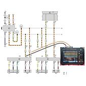
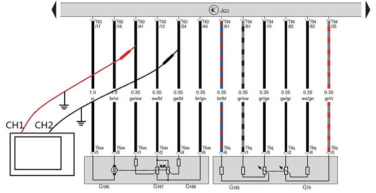
In the illustrated B7 circuit, the TAO3104A monitors both throttle position outputs simultaneously. Throttle position signal 1 is assigned to CH1, while throttle position signal 2 is assigned to CH2. Viewing both channels on the same display makes it possible to compare their direction and combined voltage throughout the test.
The measurement is intended to help check motor and sensor behavior. Rather than relying solely on an isolated value, the captured traces show how each output changes as the operating condition changes.
Interpreting the two sensor waveforms
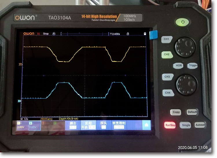
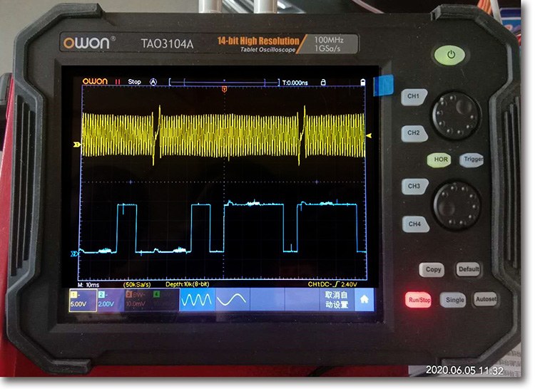
During the heavy-braking condition described in the application, the voltage for air damper position 1 on CH1 decreases and produces a concave trace. At the same time, the voltage for air damper position 2 on CH2 increases and produces a convex trace. The two outputs therefore move in opposite directions.
In this example, the sum of the CH1 and CH2 voltages is 5 V. Comparing that total provides a cross-check between the two sensor outputs. A combined result above or below 5 V is presented as a general indication of a possible sensor problem for this specific circuit and test. This value should be understood as part of the documented example rather than a universal threshold for every vehicle or sensor design.
What to review on the display
- Whether the CH1 voltage decreases under the described operating condition.
- Whether the CH2 voltage increases at the same time.
- Whether the two traces retain their opposing concave and convex behavior.
- Whether the combined voltage remains at the 5 V value specified for this example.
- Whether the recorded waveform contains brief irregularities that may not be apparent from a static reading.
Why the TAO3000 series suits waveform analysis
The four-channel TAO3000 series provides bandwidth up to 120 MHz and a maximum real-time sampling rate of 1 GSa/s. Its hardware ADC offers 14-bit vertical resolution, while the record length reaches 40M and the waveform refresh rate reaches 75,000 waveforms per second. These characteristics support detailed observation of small signal changes, longer acquisitions, and exceptional waveform events.
Low background noise further supports small-signal capture. For automotive work involving two related sensor outputs, the four-channel configuration also leaves additional channels available for observing other signals within the instrument's channel capacity.
Triggering, decoding, and waveform processing
The TAO3000 series supports Edge, Video, Pulse, Slope, Runt, Windows, Timeout, I2C, SPI, RS232/UART, CAN, and Nth Edge trigger modes. Serial bus decoding is available for I2C, SPI, RS232/UART, and CAN.
Its waveform processing functions include addition, subtraction, multiplication, division, FFT, FFTrms, integration, differentiation, square root, and user-defined functions. Digital filter options include low-pass, high-pass, band-pass, and band-reject filters. The series also supports SCPI and LabVIEW.
An 8-inch, 800 × 600-pixel multi-point touchscreen provides the primary display and control interface. Available connections include USB host, USB device, LAN, and optional Wi-Fi. The built-in Wi-Fi capability described for the series allows connection from a mobile device for screen display and control, waveform storage and viewing through the app, sharing, and collaborative analysis.
Additional automotive sensor applications
The TAO3104A application also includes captured waveforms from a magneto-electric crankshaft sensor and a Hall camshaft sensor. This demonstrates that the same oscilloscope platform can be used to examine several automotive sensor signal types, not only the dual throttle opening sensor.
Two-channel TAO3000 measurement option
The two-channel TAO3000 series combines a digital storage oscilloscope with a built-in 4½-digit multimeter. The multimeter interface can appear on the same screen as the oscilloscope, allowing both measurement modes to be accessed from one device.
Its multimeter data-logging function can record values over an extended period and export the results as a CSV file. This combination provides another operating method for automotive maintenance tasks when both waveform observation and multimeter measurements are required.
Summary
Automotive throttle sensor testing with the TAO3104A centers on simultaneous observation of two related outputs. In the documented B7 example, CH1 decreases while CH2 increases, and their combined voltage is evaluated against 5 V. The TAO3000 series supports this analysis with high-resolution acquisition, long waveform storage, a fast refresh rate, multiple triggers, serial decoding, mathematical functions, and digital filtering.
By displaying signal movement over time, the oscilloscope provides a clearer view of sensor interaction than a single static measurement. It can also be applied to crankshaft and Hall camshaft sensor waveforms, making the platform relevant to a broader range of automotive sensor diagnostic tasks.