The coating adhesion tester is an essential instrument for evaluating the quality of paints, varnishes, and protective coating systems.. A coating must remain bonded to its substrate—or to the layer beneath it in a multi-coat system—to provide its intended protection and finish. Coating adhesion test methods help inspectors assess that bond using procedures suited to the substrate, coating system, test location, and required level of measurement.
No single method is appropriate for every inspection task. Some techniques provide a rapid, practical indication of adhesion, while others generate a tensile pull-off result. Test results should always be interpreted within the context of the selected method, the equipment used, the coating condition, and the substrate.
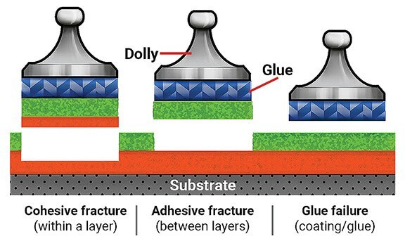
After a test, documenting the fracture pattern is important. Adhesive failure occurs at the interface between the coating and substrate, or between coating layers. Cohesive failure occurs within the coating film or substrate itself. Glue failure refers to visible separation within the adhesive used to attach a pull-off fixture. Recording the nature of failure provides useful context beyond a rating or force value alone.
Knife Testing for a Quick Adhesion Check
A knife test is a simple field-oriented method used to make a general assessment of how readily a coating can be lifted from a substrate or an underlying layer. An X-cut is made through the coating down to the substrate. The inspector then uses the knife point at the cut intersection to attempt to lift the coating.
The assessment considers both the difficulty of removal and the amount of coating removed. Because this approach depends substantially on the inspector’s technique and judgment, it is subjective. A coating with high cohesive strength may respond differently from a brittle coating, even when their apparent adhesion differs. Knife-test findings should therefore not be treated as directly interchangeable with tape or pull-off results.
ASTM D6677 describes a standard method for evaluating adhesion by knife.
Tape Tests: X-Cut and Cross-Hatch Methods
Tape testing is commonly used on metal substrates. Pressure-sensitive tape is applied over cuts made through the coating and then removed. The cut area is inspected for coating removal from the substrate or from the layer below. ASTM D3359 covers rating adhesion by tape test. Careful cutting is essential because the cuts must reach the substrate without introducing avoidable damage outside the intended pattern.
X-Cut Tape Test
The X-cut tape test is primarily intended for job-site use. A sharp cutting tool creates an X through the coating to the substrate, using a straightedge to help maintain straight cuts. Tape is centered over the cut intersection and removed rapidly. The inspector then examines and rates the tested area.
Cross-Hatch Tape Test
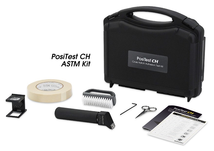
The cross-hatch tape test uses intersecting parallel cuts rather than a single X pattern. It is primarily used in laboratory settings for coatings below 5 mils, or 125 microns, in thickness. A cutting guide or multi-blade cross-hatch cutter helps produce properly spaced and parallel incisions. Once tape has been applied and removed, the amount of coating detached from the grid is inspected and rated.
Pull-Off Adhesion Testing
A pull-off adhesion test provides a more quantitative approach. A loading fixture, often called a dolly or stub, is attached to the coating with an adhesive. A portable tester applies an increasing load until the dolly is pulled off, or until the test reaches the load sustained by the assembly.
The reported result is tensile strength, typically expressed in psi or MPa. The separation occurs along the weakest plane in the complete system of dolly, adhesive, coating layers, and substrate. For that reason, examination of the exposed fracture surface is an essential part of the test record.
Pull-off testing emphasizes tensile stress, whereas knife and scrape approaches involve different loading conditions. Results from different instruments, or from coatings on substrates with different stiffness, may not be directly comparable. Repeatability is best supported when the pull force is perpendicular to the tested surface.
Portable pull-off testers may use mechanical, hydraulic, or pneumatic loading. Dolly size can also be selected for the measurement need. The source material notes that 20 mm dollies are suitable for typical bond strengths on metal, plastic, and wood, while 50 mm dollies are more suited to lower-bond-strength coatings on masonry such as concrete.
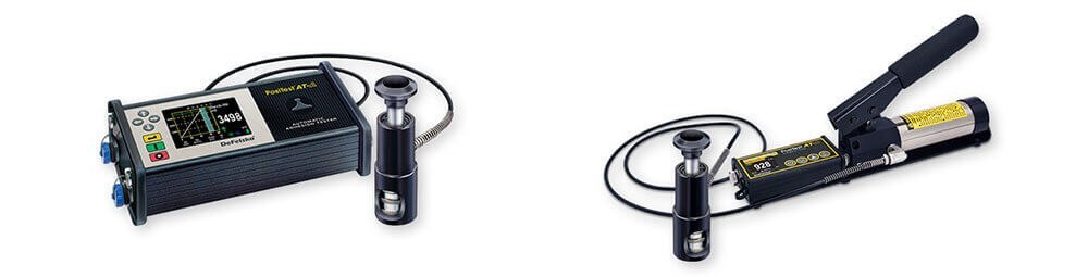
DeFelsko lists the PosiTest AT in Manual PosiTest AT-M and Automatic PosiTest AT-A versions for pull-off adhesion testing on metal, wood, concrete, and other rigid substrates. ASTM D4541 and ISO 4624 describe pull-off testing for coating adhesion.
Scrape and Other Adhesion Evaluations
A scrape test is generally a laboratory procedure for smooth, flat coated panels. The panel is moved beneath a rounded stylus or loop under progressively increasing load until the coating is removed. ASTM D2197 addresses adhesion of organic coatings by scrape adhesion.
Other evaluations may combine adhesion with flexibility, tensile behavior, impact resistance, or chemical resistance. Bending, deformation, and chip-off observations can reveal coating fracture or loss of bond during service-related stress. These approaches should be selected according to the coating system and the property that needs to be evaluated.
Selecting the Appropriate Test Method
Choose a adhesion tester based on the inspection objective. A knife or X-cut tape test may support a quick practical assessment. A cross-hatch test is useful for suitable thinner coatings in a controlled setting. A pull-off test is appropriate when a tensile measurement and fracture analysis are required. In every case, use the applicable method consistently and record the test conditions, observed coating removal, and failure mode to make results more meaningful.