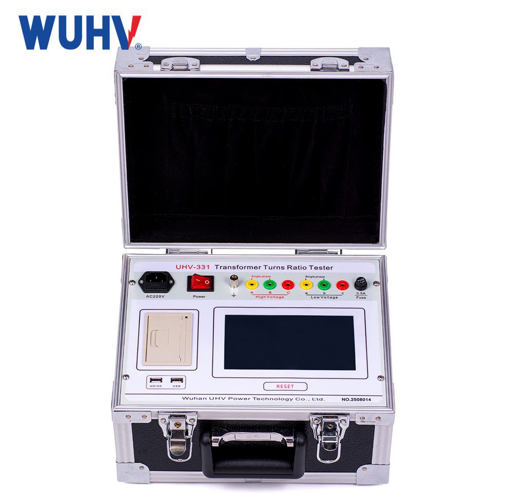
An automatic transformer turns ratio tester is used to check transformer ratios, detect deviations related to winding connections, and provide data for transformer testing. To obtain reliable measurement results, operators should follow the correct procedure, from preparation and equipment isolation to connection, testing, result verification, and data storage.
This article focuses on the procedure for using an automatic transformer turns ratio tester and the key factors that should be controlled at each stage.
What Is an Automatic Transformer Turns Ratio Tester Used For ?
An automatic transformer turns ratio tester is used to measure the voltage ratio between transformer windings. The instrument typically applies a test signal to one winding, measures the response on the other side, and automatically calculates the transformer turns ratio.
Depending on the model, the instrument may also provide additional functions, such as checking the vector group, phase angle, or performing measurements on single-phase and three-phase transformers.
Measurement results should be compared with technical specifications, equipment records, and applicable testing requirements for the specific transformer.
Procedure for Using an Automatic Transformer Turns Ratio Tester
Step 1: Prepare the Equipment and Confirm Safety Conditions
Before starting the measurement, inspect the condition of the tester, test leads, and clamps. Do not use damaged test leads, loose connectors, or components showing signs of insulation deterioration.
The transformer must be placed in a condition suitable for testing in accordance with the organization's safety procedures. The operator should confirm that the equipment has been isolated from the electrical system before making any connections.
Items to check include:
Transformer isolation status
Grounding requirements and on-site safety procedures
Condition of test leads and clamps
Power supply for the tester
Transformer technical information and winding connection diagram
The measurement should not begin until the transformer configuration and the terminals to be tested have been clearly identified.
Step 2: Identify Transformer Parameters and Configuration
Before connecting the tester, the transformer type and information relevant to the test should be identified.
The operator should check:
Whether the transformer is single-phase or three-phase
Rated voltage of the windings
Rated transformer ratio
Number of terminals and terminal markings
Winding configuration or vector group, where applicable
Tap positions to be tested
This information helps ensure that the correct measurement mode is selected and that the connections are made properly.
For transformers equipped with a tap changer, the range and sequence of tap positions to be tested should be determined in advance. Measuring only one position and using the result to represent all operating tap positions is not recommended.
Step 3: Connect the Tester to the Transformer
This step directly affects the reliability of the measurement results.
The test leads must be connected correctly to the primary and secondary terminals according to the tester's connection diagram and the transformer configuration. The clamps should make secure contact to prevent poor connections or incorrect terminal placement.
When making the connections, pay attention to the following:
Verify the correct terminal markings
Connect the high-voltage and low-voltage sides according to the instrument instructions
Ensure good contact between the clamps and terminals
Avoid unnecessary tension or overlapping of test leads
Check all connections again before starting the measurement
For three-phase transformers, particular attention should be paid to phase sequence and winding configuration. Errors at this stage may produce abnormal results or make the measurement data difficult to interpret.
Step 4: Set the Measurement Mode
After completing the connections, turn on the instrument and select the appropriate test mode.
Depending on the model of the transformer winding tester, the operator may need to enter or select information such as:
Transformer type
Single-phase or three-phase measurement mode
Winding configuration
Tap position being tested
Other parameters required by the instrument interface
All settings should be checked before starting the measurement. Selecting an incorrect configuration may produce unsuitable results even when the physical connections are correct.
Step 5: Perform the Transformer Ratio Measurement
Once the safety conditions, connections, and settings have been verified, the measurement can be started.
The tester applies a test signal, receives the corresponding signal from the transformer windings, and calculates the transformer ratio according to the instrument's operating function.
During the measurement, do not:
Disconnect or change the test leads.
Move the clamps.
Change the transformer configuration.
Turn off the instrument before the measurement is complete.
The operator should wait for the instrument to complete the measurement cycle before reading and saving the results.
If the instrument displays a warning or an abnormal result, the connections and settings should be checked before concluding that the transformer has a fault.
Step 6: Check and Compare the Results
After the measurement is complete, the results should be compared with the rated ratio, technical specifications, and applicable testing requirements.
If deviations are observed, the following checks are recommended:
Recheck the connection diagram.
Inspect the clamps and terminal contact.
Confirm the transformer configuration entered into the instrument.
Verify the tap position being tested.
Repeat the measurement.
Repeating the test can help eliminate errors caused by operator handling or incorrect connections.
Transformer ratio results should also be considered together with other test data when evaluating the overall condition of a transformer.
Step 7: Record and Store the Data
After confirming the results, the measurement data should be saved or documented for future comparison.
The recorded information should include:
Transformer identification number or location
Date of the measurement
Tap position tested
Measurement results for each phase or position
Relevant test conditions
Notes regarding abnormal results
For instruments with internal memory or data export functions, results should be organized by equipment to make it easier to monitor and compare data from different inspection periods.
Step 8: Complete the Test and Disconnect the Equipment
After the test is complete, turn off the instrument or exit the measurement mode according to the manufacturer's instructions.
Test leads should only be disconnected after confirming that the test has ended and that safe conditions have been established.
The test leads should be removed in an appropriate sequence and then inspected and stored properly to prevent bending, excessive tension, or damage to the connectors.
Factors to Control During the Measurement Process
Even when the correct procedure is followed, several factors may affect the results or make the data more difficult to evaluate.
Common factors include:
Incorrect terminal connections or phase sequence
Poor clamp contact
Incorrect transformer configuration
Testing the wrong tap position
Electromagnetic interference at the test location
Unsuitable Equipment or Test Lead Conditions
When abnormal results occur, these factors should be checked before making conclusions about the condition of the transformer windings or configuration.
Inspecting the Equipment Before Use
To maintain stable performance, an automatic transformer turns ratio tester should be inspected regularly.
Users should check the condition of:
The tester and display
Test leads
Clamps and connectors
Power supply or battery
Memory and data storage functions, if available
The equipment should also be calibrated and maintained according to the manufacturer's instructions or the organization's equipment management requirements.
Summary of the Automatic Transformer Turns Ratio Testing Procedure
Isolate the transformer and confirm safety → Identify the transformer configuration → Check the tester and test leads → Make the connections → Set the measurement mode → Perform the measurement → Compare the results → Save the data → Disconnect and store the equipment.
Standardizing this procedure helps reduce operational errors and maintain consistency between different testing sessions.
Frequently Asked Questions
Can the transformer ratio be measured without checking the winding connection diagram ?
This is not recommended. The correct terminals and transformer configuration should be identified before connecting the tester. Incorrect connections may lead to inaccurate results or data that are difficult to interpret.
What should be done if the measurement result is abnormal ?
The test leads, clamps, connection diagram, instrument settings, and tap position should be checked before repeating the measurement.
Is it necessary to test all transformer tap positions ?
This depends on the transformer type and the applicable testing requirements. For transformers equipped with a tap changer, the testing range should be determined according to the relevant technical procedure.
Can the overall condition of a transformer be evaluated using only the transformer ratio ?
No. Depending on the purpose of the assessment, transformer test equipment may need to be used together with other tests in accordance with the applicable technical requirements.