1. Reasons for Choosing Analog Oscilloscope
An oscilloscope is a device that displays and analyzes the waveform of an electrical signal over time. The vertical (Y) axis represents voltage, the horizontal (X) axis represents time, and in some cases, the Z axis represents the intensity of the signal.
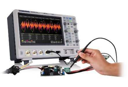
Although digital oscilloscopes are widely used today, analog oscilloscopes are still preferred in applications that require a visual, smooth, and accurate display of real-time signals. They are especially useful in equipment maintenance and repair work where transient or abnormal signals need to be observed.
The outstanding advantages of analog oscilloscopes include:
Smooth display of waveforms changing over time.
Capable of displaying multiple signals simultaneously.
Some models support color display, zoom in/out, and computer connection.
2. Operating Principle of Analog Oscilloscope
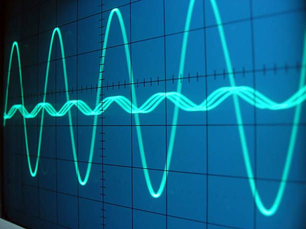
When the probe is connected to the circuit, the voltage signal is fed to the vertical system:
2.1. Vertical signal processing
An attenuator or amplifier adjusts the signal amplitude based on the volts/div setting.
The signal then drives the electron beam in the CRT (Cathode Ray Tube), creating a bright spot on the screen.
Positive voltages move the spot up, negative voltages move it down.
2.2. Activation and horizontal scanning
The signal is also sent to the trigger circuit to initiate the horizontal sweep.
The trigger ensures that the starting point of the sweep always coincides with a fixed point on the periodic signal, creating a stable waveform on the screen.
Horizontal sweep causes the light point to move from left to right, at a speed that can reach 500,000 times per second.
2.3. Create waveforms on screen
The combination of vertical and horizontal control systems creates a time-based signal graph on the CRT screen.
Thanks to the trigger system, the signal image is kept stable, making it easy to observe and analyze.
3. Components and Function Keys on an Analog Oscilloscope
POWER button: Turns the device on/off.
Intensity: Adjusts the brightness of the trace on the screen.
Focus: Adjusts the sharpness of the displayed signal.
1 kHz signal source: Used to check and calibrate the probe.
Vertical Position: Moves the signal up or down on the screen.
Horizontal Position: Moves the signal left or right on the screen.
Volts/Div: Selects the voltage level per vertical division on the Y-axis.
AC/DC/GND coupling switch:
DC: Displays the full signal (both DC and AC components).
AC: Filters out the DC component, showing only the AC signal.
GND: Disconnects the signal, displays a reference baseline.
CH1 input: Connects the signal to Channel 1.
CH2 input: Connects the signal to Channel 2.
Channel selector (CH1 / CH2 / Dual): Selects which channel(s) to display.
Magnifier (X5 or X10): Enlarges the signal for better viewing.
Sec/Div: Sets the time per horizontal division on the X-axis (ms, µs, ns).
Trigger Level: Sets the voltage level at which the sweep is triggered.
Trigger Source: Selects the trigger signal source (CH1, CH2, or external).
Trigger Mode: Selects the trigger mode: Auto, Normal, or Single.
4. Instructions for Using Analog Oscilloscope
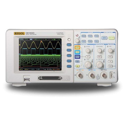
To use an analog oscilloscope effectively, the following steps should be performed in sequence:
4.1. Set signal amplitude
Use Volts/div to adjust the waveform height so that the signal fits the screen.
If the signal is too small, it can be amplified; if too large, it needs to be attenuated.
4.2. Set display time
Use Sec/div to adjust the time interval each horizontal cell represents. Too small a time interval will make the wave too stretched, too large a time interval will make it compressed.
4.3. Enable trigger mode
Adjust the Trigger level to stabilize the waveform image. Make the oscilloscope start scanning from the same point in the signal cycle.
4.4. Display Adjustment
Use the Focus and Intensity knobs to ensure the waveform is clear and easy to see.
5. Conclude
The analog oscilloscope is an important tool in the analysis of electrical signals that change in real time. Despite the development of digital technology, this instrument still plays an essential role in many electronic maintenance, repair and technical analysis applications.
Contact us for advice now:
EMIN Group is the official distributor of analog and digital oscilloscopes from leading brands such as: Tektronix, OWON, RIGOL, EZ, PINTEK.
With a team of highly specialized technicians, we are always ready to advise on choosing the right equipment and provide detailed and dedicated instructions for use.