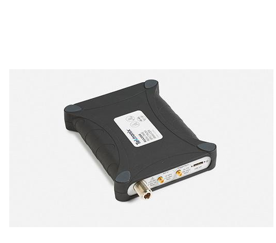
SignalVu-PC application-specific options SignalVu-PC-SVE requires the Microsoft Windows 7 or 8/8.1, 64-bit operating system. The base software is free, included with the instrument, and is also available to download from www.tek.com. Option keys are sent by email which you then enter into the application. Fully functional trial options can be activated locally for 30 days.
The following SignalVu-PC-SVE options add functionality and value to your measurement solution:
- Option SVA: AM/FM/PM/Direct audio analysis - Option SVT: Settling Time (frequency and phase) measurement - Option SVM: General purpose modulation analysis - Option SVP: Advanced Signal Analysis (including pulse measurements) - Option SVO: Flexible OFDM Analysis - Option SV23: WLAN 802.11a/b/g/j/p measurement application - Option SV24: WLAN 802.11n measurement application (requires option SV23) - Option SV25: WLAN 802.11ac measurement application (requires option SV24). Limited to 40 MHz bandwidth on RSA306 - Option SV26: APCO P25 measurement application - Option SV27: Bluetooth Basic LE Tx measurement - Option MAP: Mapping and signal strength - Option CON: SignalVu-PC live link to the MDO4000B series mixed-domain oscilloscopes - Option SIGNALVU-PC-SVE SV2C: Live Link to MDO4000B and WLAN 802.11a/b/g/j/p/n/ac measurements (includes options CON, SV23, SV24 and SV25)
Service options
- Opt. C3: Calibration Service 3 Years - Opt. C5: Calibration Service 5 Years - Opt. D1: Calibration Data Report - Opt. D3: Calibration Data Report 3 Years (with Opt. C3) - Opt. D5: Calibration Data Report 5 Years (with Opt. C5) - Opt. R3: Repair Service 3 Years (including warranty) - Opt. R5: Repair Service 5 Years (including warranty)
Recommended accessories
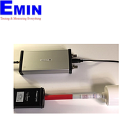
- RSA300CASE: Soft case with shoulder-strap - RSA300TRANSIT: Hard-sided transit case for RSA300 with room for USB cable and small accessories. Pelican model Stormcase iM2100 - RSA306RACK: Rackmount with slots for two RSA306. 19 inch rack with cover for unused slot - 119-6609-xx: BNC whip antenna - 103-0045-xx: N-BNC adapter - 119-6594-xx: Beam antenna, 824 MHz to 896 MHz - 119-6595-xx: Beam antenna, 896 MHz to 960 MHz - 119-6596-xx: Beam antenna, 1710 MHz to 1880 MHz - 119-6597-xx: Beam antenna, 1850 MHz to 1990 MHz - 119-6970-xx: Magnetic mount antenna, 824 MHz to 2170 MHz (requires adapter 103-0449-00) - 119-7246-xx: Pre-filter, general purpose, 824 MHz to 2500 MHz, Type-N (f) connector - 119-7426-xx: Pre-filter, general purpose, 2400 MHz to 6200 MHz, Type-N (f) connector - 012-0482-xx: Cable, 50 Ω, BNC (m) 3 foot (91 cm) - 174-4977-xx: Cable, 50 Ω, straight Type-N (m) and angled Type-N (m) connector, 1.6 foot (50 cm) - 174-5002-xx: Cable, 50 Ω, Type-N (m) to Type-N (m) connector, 3 foot (91 cm) - 119-4146-xx: EMCO E/H-field probes
Specifications
Specifications are valid within the following conditions:
Operate the instrument in an environment that meets the temperature, altitude, and humidity characteristics listed in these specifications.
Warm up time is 30 minutes after connecting to the PC and starting the SignalVu application.
Frequency
RF input frequency range
9 kHz to 6.2 GHz
Frequency reference accuracy
Initial
±3 ppm + aging (18 °C to 28 °C ambient, after 20 minute warm up)
±25 ppm + aging (-10 °C to 55 °C ambient, after 20 minute warm up), typical
Minimum signal duration for 100% probability of detection
100 μs
Span: 40 MHz, RBW = Auto, Max-hold on
Due to the non-deterministic execution time of programs running under the Microsoft Windows OS, this specification may not be met when the host PC is heavily loaded with other processing tasks
Span range (continuous processing)
1 kHz to 40 MHz
Span range (swept)
Up to maximum frequency range of instrument
Dwell time per step
50 ms to 100 s
Trace processing
Color-graded bitmap, +Peak, -Peak, average
Trace length
801, 2401, 4001, 10401
RBW range
1 kHz to 10 MHz
DPX Spectrogram display
Trace detection
+Peak, -Peak, Average(VRMS)
Trace length, memory depth
801 (60,000 traces)
2401 (20,000 traces)
4001 (12,000 traces)
Time resolution per line
50 ms to 6400 s, user selectable
Analog modulation analysis (standard)
AM demodulation accuracy, typical
±2%
0 dBm input at center, carrier frequency 1 GHz, 1kHz/5kHz input/modulated frequency, 10% to 60% modulation depth
0 dBm input power level, reference level = 10 dBm
FM demodulation accuracy, typical
±3%
0 dBm input at center, carrier frequency 1 GHz, 400Hz/1kHz input/modulated frequency
0 dBm input power level, reference level = 10 dBm
PM demodulation accuracy, typical
±1% of measurement bandwidth
0 dBm input at center, carrier frequency 1 GHz, 1kHz/5kHz input/modulated frequency
0 dBm input power level, reference level = 10 dBm
SignalVu-PC options
AM/FM/PM and direct audio measurement (Option SVA)
Carrier frequency range (for modulation and audio measurements)
(1/2 × audio analysis bandwidth) to maximum input frequency
Maximum audio frequency span
10 MHz
FM measurements (Mod. index >0.1)
Carrier Power, Carrier Frequency Error, Audio Frequency, Deviation (+Peak, -Peak, Peak-Peak/2, RMS), SINAD, Modulation Distortion, S/N, Total Harmonic Distortion, Total Non-harmonic Distortion, Hum and Noise
AM measurements
Carrier Power, Audio Frequency, Modulation Depth (+Peak, -Peak, Peak-Peak/2, RMS), SINAD, Modulation Distortion, S/N, Total Harmonic Distortion, Total Non-harmonic Distortion, Hum and Noise
PM measurements
Carrier Power, Carrier Frequency Error, Audio Frequency, Deviation (+Peak, -Peak, Peak-Peak/2, RMS), SINAD, Modulation Distortion, S/N, Total Harmonic Distortion, Total Non-harmonic Distortion, Hum and Noise
Direct audio measurements
Signal power, Audio frequency (+Peak, -Peak, Peak-Peak/2, RMS), SINAD, Modulation distortion, S/N, Total harmonic distortion, Total non-harmonic distortion, Hum and Noise
Audio filters
Low pass: 0.3, 3, 15, 30, 80, 300, and user-entered up to 0.9 × audio bandwidth
High pass: 20, 50, 300, 400, and user-entered up to 0.9 × audio bandwidth
Standard: CCITT, C-Message
De-emphasis (μs): 25, 50, 75, 750, and user-entered
File: User-supplied .TXT or .CSV file of amplitude/frequency pairs. Maximum 1000 pairs
Performance characteristics, typical
Conditions: Unless otherwise stated, performance is given for:
Modulation rate = 5 kHz
AM depth: 50%
PM deviation 0.628 Radians
FM
AM
PM
Conditions
Carrier Power accuracy
Refer to instrument amplitude accuracy
Carrier Frequency accuracy
± 7 Hz + (transmitter frequency × ref. freq. error)
Refer to instrument frequency accuracy
± 2 Hz + (transmitter frequency × ref. freq. error)
FM deviation: 5 kHz / 100 kHz
Depth of Modulation accuracy
NA
± 0.5%
NA
Rate: 5 kHz Depth: 50%
Deviation accuracy
± (2% × (rate + deviation))
NA
± 3%
FM deviation: 100 kHz
Rate accuracy
± 0.2 Hz
± 0.2 Hz
± 0.2 Hz
FM deviation: 5 kHz / 100 kHz
Residual THD
0.5%
0.5%
NA
FM Deviation: 5 kHz / 100 kHz Rate: 1 kHz
Residual SINAD
49 dB 40 dB
56 dB
42 dB
FM deviation 5 kHz FM deviation 100 kHz Rate: 1 kHz
Pulse measurements (Option SVP)
Measurements (nominal)
Average On Power, Peak Power, Average Transmitted Power, Pulse Width, Rise Time, Fall Time, Repetition Interval(seconds), Repetition Interval (Hz), Duty Factor (%), Duty Factor (ratio), Ripple, Droop, Pulse-Pulse Frequency Difference, Pulse-Pulse Phase Difference, RMS Frequency Error, Max Frequency Error, RMS Phase Error, Max Phase Error, Frequency Deviation, Phase Deviation, Time Stamp, Delta Frequency, Impulse Response, Overshoot
Minimum pulse width for detection
150 ns
Average ON power at 18 °C to 28 °C, typical
±1.0 dB + absolute amplitude accuracy
For pulses of 300 ns width or greater, duty cycles of .5 to .001, and S/N ratio ≥ 30 dB
Duty factor, typical
±0.2% of reading
For pulses of 450 ns width or greater, duty cycles of .5 to .001, and S/N ratio ≥ 30 dB
Average transmitted power, typical
±1.0 dB + absolute amplitude accuracy
For pulses of 300 ns width or greater, duty cycles of .5 to .001, and S/N ratio ≥ 30 dB
Peak pulse power, typical
±1.5 dB + absolute amplitude accuracy
For pulses of 300 ns width or greater, duty cycles of .5 to .001, and S/N ratio ≥ 30 dB
Pulse width, typical
±0.25% of reading
For pulses of 450 ns width or greater, duty cycles of .5 to .001, and S/N ratio ≥ 30 dB
General purpose digital modulation analysis (Option SVM)
Constellation, Demod I&Q vs. Time, Error Vector Magnitude (EVM) vs. Time, Eye Diagram, Frequency Deviation vs. Time, Magnitude Error vs. Time, Phase Error vs. Time, Signal Quality, Symbol Table, Trellis Diagram
Symbol rate range
1 k symbols/s to 40 M symbols/s
Modulated signal must be contained entirely within the acquisition bandwidth
QPSK Residual EVM (center frequency = 2 GHz), typical
1.1 % (100 kHz symbol rate)
1.1 % (1 MHz symbol rate)
1.2 % (10 MHz symbol rate)
2.5 % (30 MHz symbol rate)
400 symbols measurement length, 20 Averages, normalization reference = maximum symbol magnitude
256 QAM Residual EVM (center frequency = 2 GHz), typical
0.8 % (10 MHz symbol rate)
1.5 % (30 MHz symbol rate)
400 symbols measurement length, 20 Averages, normalization reference = maximum symbol magnitude
WLAN Measurements, 802.11a/b/g/j/p (Option SV23)
Measurements
WLAN power vs. time; WLAN symbol table; WLAN constellation; spectrum emission mask; error vector magnitude (EVM) vs. symbol (or time), vs subcarrier (or frequency); mag error vs symbol (or time), vs. subcarrier (or frequency); phase error vs symbol (or time), vs. subcarrier (or frequency); channel frequency response vs. symbol (or time), vs. subcarrier (or frequency); spectral flatness vs. symbol (or time), vs. subcarrier (or frequency)
Input signal level optimized for best EVM, average of 20 bursts, ≥16 symbols each
Residual EVM - 802.11b, CCK-11, typical
2.4 GHz, 11 Mbps: 2.0 %
Input signal level optimized for best EVM, average of 1,000 chips, BT = .61
WLAN Measurements 802.11n (Option SV24)
Measurements
WLAN power vs. time; WLAN symbol table; WLAN constellation; spectrum emission mask; error vector magnitude (EVM) vs. symbol (or time), vs subcarrier (or frequency); mag error vs symbol (or time), vs. subcarrier (or frequency); phase error vs symbol (or time), vs. subcarrier (or frequency); channel frequency response vs. symbol (or time), vs. subcarrier (or frequency); spectral flatness vs. symbol (or time), vs. subcarrier (or frequency)
EVM performance - 802.11n, 64-QAM, typical
2.4 GHz, 40 MHz BW: -35 dB
5.8 GHz, 40 MHz BW: -35 dB
Input signal level optimized for best EVM, average of 20 bursts, ≥16 symbols each
WLAN Measurements 802.11ac (Option SV25)
Measurements
WLAN power vs. time; WLAN symbol table; WLAN constellation; spectrum emission mask; error vector magnitude (EVM) vs. symbol (or time), vs subcarrier (or frequency); mag error vs symbol (or time), vs. subcarrier (or frequency); phase error vs symbol (or time), vs. subcarrier (or frequency); channel frequency response vs. symbol (or time), vs. subcarrier (or frequency); spectral flatness vs. symbol (or time), vs. subcarrier (or frequency)
EVM performance - 802.11ac, 256-QAM, typical
5.8 GHz, 40 MHz BW : -35 dB
Input signal level optimized for best EVM, average of 20 bursts, ≥16 symbols each
APCO P25 Measurements (Option SV26)
Measurements
RF output power, operating frequency accuracy, modulation emission spectrum, unwanted emissions spurious, adjacent channel power ratio, frequency deviation, modulation fidelity, frequency error, eye diagram, symbol table, symbol rate accuracy, transmitter power and encoder attack time, transmitter throughput delay, frequency deviation vs. time, power vs. time, transient frequency behavior, HCPM transmitter logical channel peak adjacent channel power ratio, HCPM transmitter logical channel off slot power, HCPM transmitter logical channel power envelope, HCPM transmitter logical channel time alignment, cross-correlated markers
Modulation fidelity, typical
C4FM = 1.3%
HCPM = 0.8%
HDQPSK = 2.5%
Input signal level is optimized for best modulation fidelity.
Bluetooth Measurements (Option SV27)
Modulation formats
Basic Rate, Bluetooth Low Energy, Enhanced Data Rate - Revision 4.1.1
Measurements
Peak Power, Average Power, Adjacent Channel Power or InBand Emission mask, -20dB Bandwidth, Frequency Error, Modulation Characteristics including ΔF1avg (11110000), ΔF2avg (10101010), ΔF2 > 115 kHz, ΔF2/ΔF1 ratio, frequency deviation vs. time with packet and octet level measurement information, Carrier Frequency f0, Frequency Offset (Preamble and Payload), Max Frequency Offset, Frequency Drift f1-f0, Max Drift Rate fn-f0 and fn-fn-5, Center Frequency Offset Table and Frequency Drift table, color-coded Symbol table, Packet header decoding information, eye diagram, constellation diagram
Output power, In-band emissions and ACP
Level uncertainty: refer to instrument amplitude and flatness specification
Measurement range: signal level > –70 dBm
Modulation characteristics
Deviation range: ±280 kHz
Deviation uncertainty (at 0 dBm)
2 kHz + instrument frequency uncertainty (basic rate)
3 kHz + instrument frequency uncertainty (low energy)
Measurement range: Nominal channel frequency ±100 kHz
5% to 75% ±5% relative humidity (RH) from +30 °C to +40 °C (+86 °F to 104 °F)
5% to 45% RH above +40 °C to +55 °C (+86 °F to +131 °F)
Altitude
Operating
Up to 9,144 meters (30,000 feet)
Nonoperating
15,240 meters (50,000 feet)
Dynamics
Mechanical shock, operating
Half-sine mechanical shocks, 30 g peak amplitude, 11 μs duration, three drops in each direction of each axis (18 total)
Random vibration, nonoperating
0.030 g2/Hz, 10-500 Hz, 30 minutes per axis, three axes (90 minutes total)
Handling and transit
Bench handling, operating
Per MIL-PRF-28800F Class 2 operating: Rotational-edge-drops of appropriate edges on appropriate sides of the equipment
Transit drop, nonoperating
Per MIL-PRF-28800F Class 2 nonoperating: Transit drops onto six faces and four corners of the equipment, from a height of 30 cm (11.8 in.) for a total of 10 impacts