DC resistance unbalance is the difference in DC resistance between conductors in one twisted pair or between cable pairs. In Power over Ethernet (PoE) cabling, excessive unbalance can interfere with the even distribution of power and affect Ethernet data transmission.
ANSI/TIA-568.2 specifies DC resistance unbalance values for Category 5e, Category 6, and Category 6A channels. The parameter is not currently stated as a general field-testing requirement, but a project specification, customer, or cabling warranty requirement may make testing necessary.
Summary: DC resistance must be balanced within and between pairs for PoE. TIA-568 values cited for the limit are 3% or 0.20 Ω within a pair, and 7% or 0.20 Ω between pairs. Installation quality and conductor quality can contribute to unbalance. Field testing may be required by the project or warranty terms.
Why does DC resistance unbalance matter for PoE cabling?
DC resistance unbalance matters because PoE sends power as a common-mode voltage across cable pairs, where it needs to be divided evenly between conductors and pairs. Higher-power 802.3bt Type 3 and Type 4 PoE uses all four pairs, making resistance balance between pairs particularly relevant.
If the resistance difference is too high, a powered device transformer can become saturated. The resulting Ethernet signal distortion can lead to bit errors, retransmissions, or a link that does not operate.
What is the difference between within-pair and between-pair unbalance?
Within-pair unbalance compares the DC resistance of the two individual conductors in the same twisted pair. Between-pair unbalance compares the resistance characteristics of one pair with those of other pairs.
For a within-pair calculation, the DC loop resistance is the sum of the resistance of both conductors, while the unbalance is their difference. For between-pair testing, the resistance of each pair is calculated in parallel and then compared with the other pairs.
| Measurement | What is compared | Value specified in the source |
|---|---|---|
| Within-pair DC resistance unbalance | Two conductors in the same pair | Maximum 3% of total pair DC loop resistance or 0.20 Ω |
| Between-pair DC resistance unbalance | One pair against other pairs | Maximum 7% or 0.20 Ω |
Note: A value of zero would indicate perfectly matched resistances, but practical cable construction and termination conditions introduce some degree of unbalance.
What can cause DC resistance unbalance in structured cabling?
Installation practices and cable quality are cited as frequent sources of DC resistance unbalance. Bending a cable beyond its minimum bend radius, untwisting pairs too far from the termination point, and inconsistent terminations can increase the difference in resistance.
Conductor variations such as diameter, roundness, contour, or surface smoothness can also raise the risk. Cables with non-standard conductors, including copper-clad aluminum (CCA) or copper-coated steel rather than 100% copper, are described as having higher resistance and a greater risk of unbalance.
A four-pair punch-down tool that terminates all eight conductors simultaneously with equal force can help promote more consistent terminations. This does not replace following the applicable cable installation and project requirements.
How is DC resistance unbalance measured in the field?
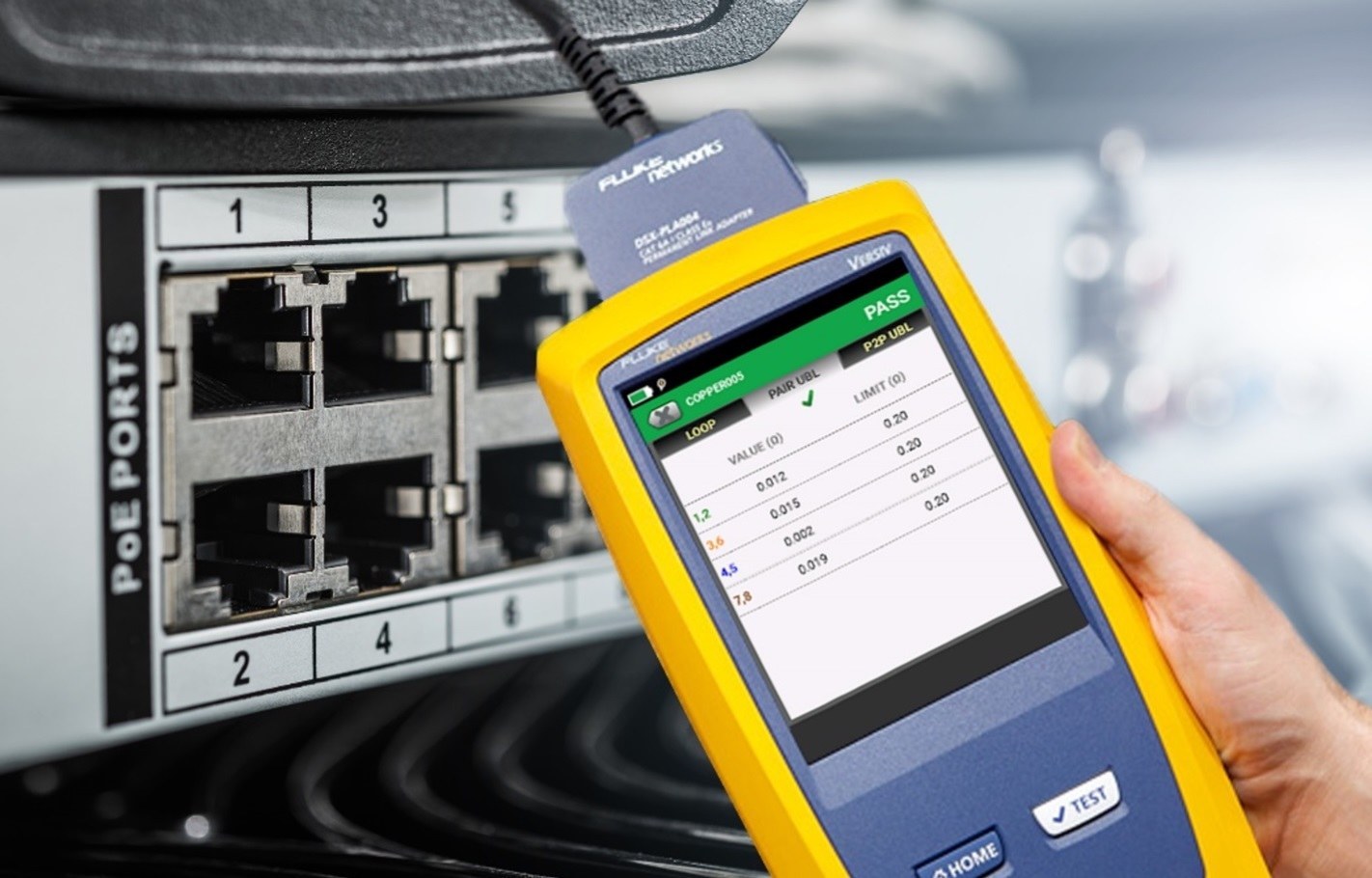
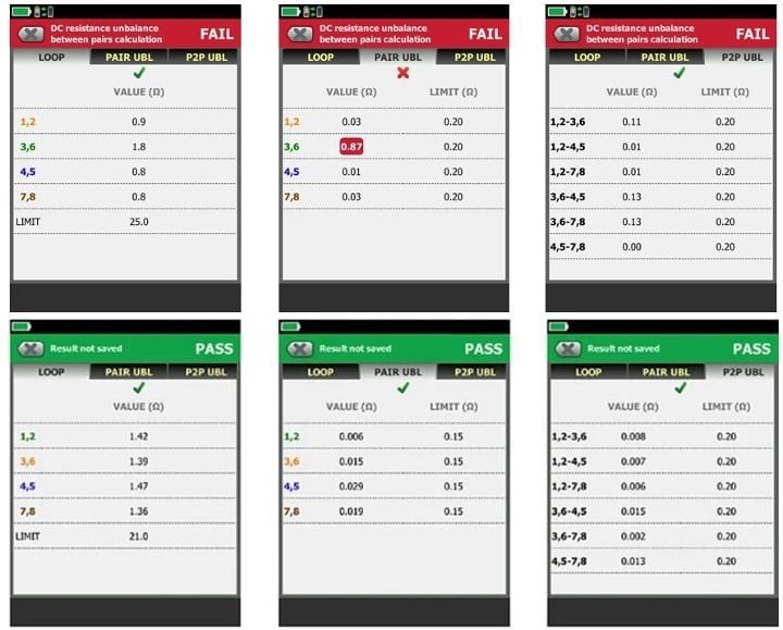
A field tester can measure conductor resistance, calculate the resistance difference, and compare the result with the applicable test limit. The Cable Analyzer is described in the source as displaying DC resistance unbalance within a pair and between pairs with its default +PoE test limit.
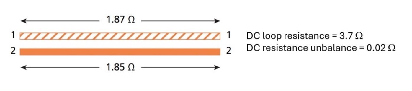
In the example provided, conductor resistances of 1.87 Ω and 1.85 Ω produce a difference of 0.02 Ω. The tester also evaluates DC loop resistance and may report results as PASS or FAIL for within-pair unbalance, identified as PAIR UBL, and between-pair unbalance, identified as P2P UBL.
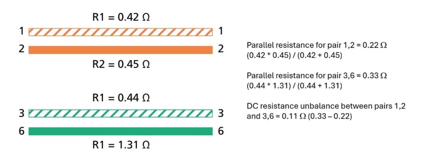
The source notes that a failure for unbalance within a pair affects the evaluation of DC loop resistance and between-pair unbalance. Reviewing the individual measurement results is therefore important when troubleshooting a failed link.
Is field testing for DC resistance unbalance required?
ANSI/TIA-568.2 specifies values used to calculate DC resistance unbalance, but the source states that it does not itself specify DC resistance unbalance as a field-testing requirement. ANSI/TIA-1152 is identified as the standard addressing field test instruments and measurements, and the source says it does not currently list this parameter as a field-testing requirement.
Testing can still be mandatory for a particular installation when it is included in the customer specification or required to obtain a cabling system warranty. The practical step is to agree on the test scope with the customer and cabling manufacturer before certification work begins.
How much additional time can DC resistance unbalance testing add?
According to the source, a full permanent-link auto test with a DSX2-8000 takes about 10 seconds. Using the default PoE+ limit to include DC resistance unbalance adds about 3 seconds, for a stated total of approximately 13 seconds.
The actual test plan should follow the agreed project requirements. Including the measurement where PoE assurance, customer acceptance, or warranty conditions call for it can identify resistance-related cabling issues before later troubleshooting is needed.