Backplane Connectors
Reliable board-to-board communication becomes critical as systems grow more modular, denser, and faster. In servers, telecom racks, industrial control platforms, and embedded equipment, the connector between daughtercards and the main interconnect structure often determines whether signal paths remain stable under real operating conditions. That is where Backplane Connectors become a key part of the design, not just a mechanical interface.
These connectors are built for applications where many signals, and sometimes power, must pass through a compact connection system across multiple boards. Compared with simpler interconnect types, they are selected with greater attention to signal integrity, mating alignment, mechanical robustness, and long-term serviceability.
Why backplane connectors matter in modular electronics
A backplane acts as the central interconnection structure in a modular system, allowing several boards to communicate through a shared architecture. The connector is the physical point that links each card to that system, so its design has a direct effect on transmission quality, assembly reliability, and maintenance convenience.
Unlike general-purpose connectors used for simpler point-to-point wiring, backplane interconnects are typically chosen for high contact density and controlled electrical performance. In many designs, they also need to support repeated insertion cycles, accurate board positioning, and stable performance under vibration or thermal variation.
How they differ from regular connectors
The main difference is not only form factor, but operating context. A regular connector may simply transfer signals between two separate components or along a cable path, while a backplane connector is usually part of a larger board-level architecture where multiple channels operate in parallel and spacing is tightly controlled.
That is why engineers often evaluate factors such as signal integrity, impedance behavior, crosstalk control, contact geometry, and mounting method much more carefully in this category. In applications where other interconnect styles are also used, it can be helpful to compare the role of backplane parts with related options such as cable assemblies or dedicated connector contacts depending on how the system is built.
Typical applications for backplane connector systems
Backplane connectors are common in equipment that uses multiple functional boards inside one enclosure or rack. Typical examples include communications hardware, storage platforms, switching systems, industrial computing, high-channel-count instrumentation, and modular control systems where boards must exchange data continuously and reliably.
They are also relevant in environments where serviceability matters. If a board may need to be replaced without redesigning the full wiring structure, a backplane-based architecture can simplify maintenance. In practical terms, this makes the category relevant not only for high-speed digital systems, but also for many industrial and test platforms that need orderly board integration inside a compact chassis.
Selection criteria: electrical, mechanical, and assembly considerations
Choosing the right connector is rarely about pin count alone. Electrical requirements may include current handling, signal density, and compatibility with high-speed differential channels. Mechanical considerations include orientation, mating stability, insertion force, and durability in applications exposed to vibration, heat, or repeated servicing.
Assembly method is another important factor. Some systems use soldered versions, while others benefit from press-fit termination to reduce thermal stress during manufacturing and support efficient installation on plated through-holes. In dense multilayer boards, the mounting approach can influence not only production flow but also long-term reliability.
Environmental exposure should not be overlooked either. For installations facing temperature variation, humidity, or continuous operation, material quality, plating, and connector retention become more important. In broader interconnect ecosystems, supporting parts such as keystone connectors or specialized interface hardware may appear elsewhere in the system, but backplane parts remain focused on structured board-level connectivity.
Examples from the available product range
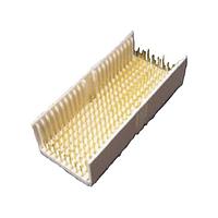
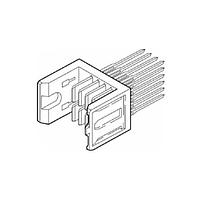
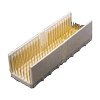
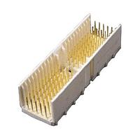
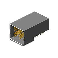
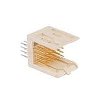
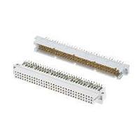
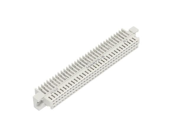
The product range in this category includes multiple connector families and layouts intended for different board architectures. Examples from 3M include the 3M MP2-HP08-41P1-TR30 Connector Backplane, 3M MP2-S120-51M1-C-LR Connector Backplane, 3M MP2-H180-54S3-S-TR30 Connector Backplane, and 3M HDC-H080-41S1-TG30 Connector Backplane. DIN-style options such as 3M DIN-032CSE-PW1-SH, 3M DIN-032RPB-DPW1-FJ, and 3M DIN-032RPA-W-SH show that the category also covers legacy and established board interconnect formats used in many designs.
For projects that need alternative layouts or manufacturer ecosystems, the range also includes the Amphenol 9236L0C40H Conn Backplane HDR 48 POS Solder ST Thru-Hole from Amphenol. These examples illustrate the variety within the category: some parts are suited to compact board arrangements, some to higher contact counts, and others to design paths where established backplane standards are still preferred.
When press-fit and soldered versions make sense
Press-fit connectors are often selected when manufacturers want to avoid soldering heat on the connector termination area or improve assembly efficiency in volume production. They can be a practical choice for multilayer PCBs and systems where consistency of hole quality and insertion process is well controlled.
Soldered versions, on the other hand, remain relevant for many designs and may align better with existing assembly workflows or product requirements. The right choice depends on PCB construction, production capability, expected service conditions, and whether field replacement or repair is part of the maintenance strategy. There is no universal answer; the connector should be matched to the total system design rather than selected in isolation.
Designing for reliability in demanding environments
In industrial and infrastructure equipment, connector performance has to remain stable over time, not only during initial testing. Vibration, thermal cycling, and moisture can all affect contact stability and mechanical retention if the wrong interconnect is used. That is why designers often prioritize secure mating behavior, durable contact surfaces, and housing materials suited to the operating environment.
For systems that combine high-density board interconnects with external test or field wiring, other connector categories such as banana and tip connectors may serve different access or measurement functions. Backplane connectors, by contrast, are intended for the internal architecture of the equipment, where structured board engagement and repeatable electrical performance are essential.
Finding the right backplane connector for your system
The most effective way to evaluate this category is to start from the architecture of the equipment: board spacing, required positions, mounting preference, service model, and expected electrical load. From there, it becomes easier to narrow the options between compact high-density series, DIN-based formats, and through-hole or other board-mount styles already represented in the product range.
A well-matched backplane connector helps support cleaner integration, more dependable communication between boards, and easier maintenance over the product lifecycle. If you are comparing options for a new design or updating an existing platform, reviewing representative parts from 3M and Amphenol is a practical way to identify the connector style that fits your mechanical and electrical requirements.
Get exclusive volume discounts, bulk pricing updates, and new product alerts delivered directly to your inbox.
By subscribing, you agree to our Terms of Service and Privacy Policy.
Direct access to our certified experts