DC Power Connectors
Reliable low-voltage power distribution depends on more than current rating alone. In real equipment, the connector must also match the mechanical layout, mating cycle expectations, mounting method, and the way power and signal lines are routed through the system. That is why DC Power Connectors are used across embedded electronics, industrial assemblies, test fixtures, control devices, and compact power interfaces where stable electrical contact matters.
This category brings together connector options designed for DC power transfer in board-level and cable-level designs. It is especially relevant when engineers need a practical balance between footprint, contact configuration, assembly method, and long-term reliability in production hardware.
Where DC power connectors fit in system design
DC connectors are commonly selected for devices powered by adapters, internal power rails, battery-backed subsystems, and modular electronics. Depending on the architecture, they may be used simply to deliver power, or to combine power distribution with adjacent low-level signal contacts in a single interface.
For applications that rely on coaxial-style input connections, engineers may also compare options in barrel connector ranges. In contrast, this category also covers board-to-board and wire-to-board styles that are often better suited to integrated assemblies, compact enclosures, or mixed signal/power layouts.
Common connector formats in this category
A useful way to evaluate this category is by how the connector is deployed in the product. Some parts are intended for cable termination and field wiring, while others are built for PCB installation with through-hole or surface-mount assembly. There are also signal/power combo formats that help reduce connector count by carrying both functions in one mated pair.
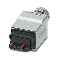
Examples from this range illustrate that variety well. The Samtec PCS2-113-01-F-D-04 and several HPFC series parts are designed around combined signal and power interfaces, while the Samtec UPS-06-07.0-02-L-V-TR and MPSC-01-40-01-7.70-01-T-V highlight higher-current board-level power strip concepts. For cable-side connection, the AMP Connectors - TE Connectivity 1-2129334-1 shows a different approach with a plug-style format and right-angle cable orientation.
Key selection criteria for engineers and buyers
When narrowing down DC power connector options, start with the electrical requirement: operating voltage, expected current, and whether the interface handles only power or both power and control signals. From there, the physical side becomes equally important, including pitch, number of contacts, mating geometry, and whether the assembly must support straight, right-angle, cable-mount, through-hole, or SMT installation.
Material and environmental considerations also affect the choice. Contact plating, housing resin, and operating temperature range can influence durability, soldering compatibility, and long-term stability. In production environments, teams often review not only nominal ratings but also how the part fits into assembly flow, inspection, field serviceability, and connector retention under repeated use.
Board-level integration and mixed power/signal layouts
Many modern electronic designs need more than a simple two-wire power entry. Compact modules, daughtercards, backplanes, and subsystem boards often require integrated power and signal routing to keep wiring organized and reduce space consumption. This is where combo connector families become especially useful, because they can simplify interconnect architecture without forcing a separate power header and signal header.
Several featured Samtec parts in this category reflect that need. Models such as the HPFC series and PCS2 series are representative of board-level connector solutions that support compact layouts and structured mating interfaces. If your project is centered on dense interconnect design, exploring the broader Samtec portfolio can help identify related connector families for stackable, modular, or mixed-contact applications.
When cable-mount DC connectors are a better fit
Not every design calls for a PCB socket strip or board-mounted power interface. In many cases, a cable-side plug is preferable, especially where removable harnesses, external power leads, or angled cable exits are needed to suit the enclosure. This is often true in serviceable devices, peripheral equipment, and compact control boxes where cable routing is a major constraint.
The AMP Connectors - TE Connectivity 1-2129334-1 is a good example of a cable-mount DC connector style within the category. For teams working with cable assemblies or power lead termination strategies, it can also be helpful to review the broader AMP Connectors - TE Connectivity range for related interconnect options used in harnessed power systems.
How DC connectors compare with other power connection types
Although the category focus here is DC distribution, connector selection often happens alongside wider power-interface decisions. Some systems need a dedicated low-voltage connector internally, but use a different format at the mains input or on rugged external interfaces. That is why connector choice should be tied to the actual electrical boundary in the product rather than treated as a generic purchasing decision.
If the application involves line-powered equipment, AC power connector options may be more appropriate on the input side. For harsher environments, higher mating forces, or more robust housings, engineers may instead assess heavy-duty power connectors. In many assemblies, these categories complement one another rather than compete directly.
Practical buying considerations for B2B sourcing
For OEM, contract manufacturing, and maintenance purchasing teams, connector selection usually extends beyond the basic technical fit. Availability, consistency across production lots, preferred mounting style, and compatibility with existing harness or PCB designs all influence the final decision. A connector that looks suitable electrically may still create unnecessary complexity if it changes tooling, board layout, or assembly workflow.
It is also useful to compare whether a part is intended as a primary power interface, a board-level subsystem connector, or a mixed-use interconnect for signal and power in one housing. Reading the product title and core specifications carefully helps clarify that role before shortlisting parts. This is especially important in a category where similar-looking connectors may serve very different positions within the system.
Choosing the right option for your application
The most effective way to evaluate this category is to begin with the actual use case: external power input, internal board interconnect, cable-to-board termination, or a hybrid signal/power interface. From there, check the mounting method, contact format, orientation, and environmental range so the selected connector supports both electrical performance and manufacturability.
Whether you are sourcing a compact socket strip for PCB integration or a plug-style connector for cable termination, this category provides a focused starting point for DC power interconnect design. Reviewing a few representative families and matching them to your layout and service requirements will usually lead to a more reliable, easier-to-build solution.
Get exclusive volume discounts, bulk pricing updates, and new product alerts delivered directly to your inbox.
By subscribing, you agree to our Terms of Service and Privacy Policy.
Direct access to our certified experts