
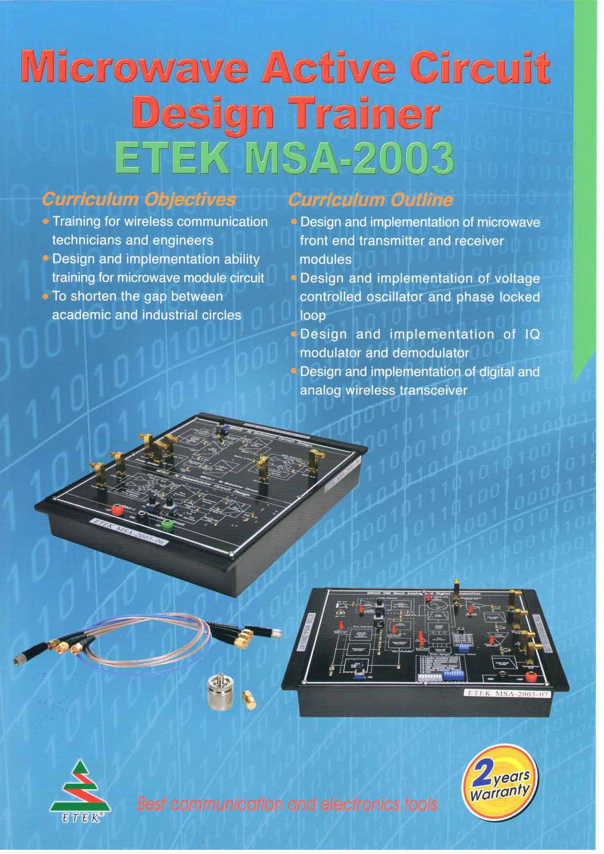
ETEK MSA-2003 Microwave Active Circuit Trainer (8 Modules)
Module One: ETEK MSA-2003-01
Chapter 1: Design and Measurement of Microstrip Line Matching Circuit
Experiment 1: Measurement of Impedance Transformer Matching Network.
(Operation Frequency: 2400 MHz; S11 < -10dB )
Experiment 2: Measurement of Single and Balanced Short Stubs Matching Network
(Operation Frequency: 2400 MHz; S11 < -10dB )
Experiment 3: Measurement of Single, Balanced and Radio Open Stubs Matching Network.
(Operation Frequency: 2400 MHz;S11 < -10dB )
Experiment 4: Measurement of and Open Stubs Matching Network.
(Operation Frequency: 2400 MHz; S11 < -10dB )
Module Two: ETEK MSA-2003-02
Chapter 2: Design and Measurement of Low Noise Amplifier (LNA)
Experiment 1: Measurement of Frequency Responses
(Operation Frequency: 2350 ~ 2450 MHz; S11 < -10dB ,S22 < -10dB , S21 > 10dB )
Experiment 2: Measurement of Noise Figure
(Operation Frequency: 2350 ~ 2450 MHz; NF < 1.8 dB)
Experiment 3: Measurement of 1 dB Compression Point
(Operation Frequency: 2400 MHz; P1dB> -15 dBm )
Chapter 3: Design and Measurement of Voltage Controlled Oscillator
Experiment 1: Measurement of Oscillation Frequency and Output Power
(Oscillation Frequency: 2350~2450 MHz; Output Power: > -5 dBm)
Experiment 2: Measurement of Phase Noise
(Phase Noise: -90 ~ -100 dBc/Hz @ 100 kHz)
Experiment 3: Measurement of Gain Factor and Tunable Bandwidth
(Gain Factor: 10 ~20 MHz/Volt; Tunable Bandwidth: 60 ~ 70 MHz)
Experiment 4: Measurement of Pushing Figure (Pushing Figure: 8 MHz/Volt)
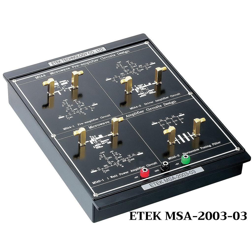
Module Three: ETEK MSA-2003-03
Chapter 4: Design and Measurement of Pre-Amplifier
Experiment 1: Measurement of Frequency Responses
(Operation Frequency: 2350 ~ 2450 MHz; S11< -10dB, S22< -10dB, S21> 10dB)
Experiment 2: Measurement of 1 dB Compression Point
(Operation Frequency: 2400 MHz; P1dB> 5dBm)
Experiment 3: Measurement of 3rd Order Intercept Point
(Operation Frequency: 2400 MHz; OIP> 25dBm)
Chapter 5: Design and Measurement of Power Amplifier
Experiment 1: Measurement of Gain Flatness
(Operation Frequency: 2350 ~ 2450 MHz; Gain Flatness:+- 1.5 dB)
Experiment 2: Measurement of 1 dB Compression Point
(Operation Frequency: 2400 MHz; P1dB > 23 dBm)
Experiment 3: Measurement of 3rd Order Output Intercept Point
(Operation Frequency: 2400 MHz; OIP3> 40 dBm)
Experiment 4: Measurement of the Ratio of Fundamental and Harmonics
(Operation Frequency: 2400 MHz:)
Module Four: ETEK MSA-2003-04
Chapter 6: Design and Measurement of Phase Locked Loop Controller
Experiment 1: LCD and Keypad Testing
(Locked Frequency Display: Locked Status Detection)
Experiment 2: MB 15E07 Control Signal Testing
(Locked Frequency: 2250 ~2350 MHz;
Stepped Frequency: 1 MHz, 10 MHz)
Chapter 7: Design and Measurement of Phase Locked Loop
Experiment 1: Measurement of Frequency Responses for Loop Filter
(3-dB Frequency: 12.5 kHz)
Experiment 2: Measurement of PLL and Phase Noise
(Phase Noise < -100 dBc/Hz @ 100 kHz)
Experiment 3: Measurement of PLL Locked Time (Locked Time < 5 ms)
Module Five: ETEK MSA-2003-05
Chapter 8: Design and Measurement of Balanced Mixer
Experiment 1: Measurement of Conversion Loss vs. LO Power
(RF: 2420 MHz, LO: 2350 MHz; Conversion Loss: < 15 dB)
Experiment 2: Measurement of Conversion Loss vs. RF Power
(RF: 2420 MHz, LO: 2350 MHz; Conversion Loss: < 15 dB, p1dB> 0dBm )
Experiment 3: Measurement of 3rd Order Intercept Point
(RF: 2420 MHz, LO: 2350 MHz; OIP> 10dBm )
Experiment 4: Measurement of IF bandwidth
(RF: 2360 ~ 2450 MHz, LO: 2350 MHz; IF bandwidth: > 100 MHz)
Experiment 5: Measurement of Isolation
(Operation Frequency: 2350 ~ 2450 MHz; Isolation: > 20 dB)
Chapter 9: Design and Measurement of Image-rejection Mixer
Experiment 1: Measurement of Conversion Loss vs. LO Power
(RF: 2420 MHz; LO: 2350 MHz; Conversion Loss: < 15 dB)
Experiment 2: Measurement of Conversion Loss vs. RF Power
(RF: 2420 MHz; LO: 2350 MHz; Conversion Loss: < 15 dB, P1dB> 5dBm )
Experiment 3: Measurement of 3rd Order Intercept Point
(RF: 2420 MHz; LO: 2350 MHz; OIP3> 15dBm )
Experiment 4: Measurement of Isolation
(Operation Frequency: 2350 ~ 2450 MHz; Isolation: > 30 dB)
Experiment 5: Measurement of Image-rejection level
(RF: 2250 ~ 2350 MHz; LO: 2350 MHz;
Image-rejection level: > 30 dB)
Module Six: ETEK MSA-2003-06
Chapter 10: Design and Measurement of IQ Modulator
Experiment 1: Measurement of PSK Modulator
(Operation Frequency: 70.7 MHz; Data Rate: >100 kbps)
Experiment 2: Measurement of QPSK Modulator
(Operation Frequency: 70.7 MHz; Data Rate: >100 kbps)
Chapter 11: Design and Measurement of IQ Demodulator
Experiment 1: Measurement of PSK Demodulator
(Operation Frequency: 70.7 MHz; Data Rate: >100 kbps)
Experiment 2: Measurement of QPSK Demodulator
(Operation Frequency: 70.7 MHz; Data Rate: >100 kbps)
Module Seven: ETEK MSA-2003-07
Chapter 12: Design and Implementation of Digital Wireless Transmitter
Experiment 1: Measurement of Output Power
(Operation Frequency: 2400 MHz; Pout> 10dBm)
Experiment 2: Measurement of Harmonics’ Output Power
(Operation Frequency: 2400 MHz; Pout< -45 dBm )
Experiment 3: Measurement of Modulation Signal
(Operation Frequency: 2400 MHz; Type of Modulation: FSK)
Module Eight: ETEK MSA-2003-08
Chapter 13: Design and Implementation of Digital Wireless Receiver
Experiment 1: Measurement of Sensitivity
(Operation Frequency: 2400 MHz; Receiver Sensitivity: > -80 dBm)
Experiment 2: Measurement of Demodulation Signal
(Operation Frequency: 2400 MHz; Type of Demodulator: FSK)
Experiment 3: Measurement of Image-rejection Ability
(Operation Frequency: 2400 MHz; Image-rejection level: > 30 dB)
Features
Get exclusive volume discounts, bulk pricing updates, and new product alerts delivered directly to your inbox.
By subscribing, you agree to our Terms of Service and Privacy Policy.
Direct access to our certified experts