Fiber ranger
Finding intermittent loss on a fiber link is rarely as simple as checking whether light is present. In practical field work, technicians often need to confirm connector condition, detect optical signal presence, and narrow down where attenuation or failure is affecting the network. This is where the Fiber ranger category becomes useful, especially in maintenance tasks for surveillance systems, structured cabling, telecom rooms, and other fiber-based installations.
Rather than focusing on one single test method, this equipment group supports everyday troubleshooting around live fiber paths, connector inspection, and quick service restoration. For teams responsible for uptime, having the right combination of detection and inspection tools can reduce guesswork and shorten repair time.
Typical situations where fiber troubleshooting tools are needed
Fiber-related faults do not always appear as a complete outage. In many installations, the real issue is a gradual increase in loss caused by contamination, poor connector mating, stress on the cable path, or damaged patching points. These problems can lead to unstable video transmission, unreliable communication links, or inconsistent network performance.
In surveillance systems, for example, an IP camera backbone may depend entirely on optical transmission. A bent section of cable, a dirty ferrule, or an improperly seated connector can create enough attenuation to cause image dropouts or signal instability. In these cases, field technicians need tools that help verify whether optical power is present and whether the connector end-face is still in acceptable condition.
What this category covers in practical terms
This category brings together equipment used to detect optical signal, inspect fiber connector end-faces, and support fault isolation during maintenance. It is especially relevant when the goal is not full certification of a fiber plant, but fast diagnosis and corrective action at the point of failure.
Some applications overlap with broader test workflows. If the task requires trace-based distance analysis on a longer span, an OTDR meter may be more appropriate. When the main requirement is insertion loss verification at defined points, an optical power meter can complement the tools in this category.
Signal detection and light presence checking
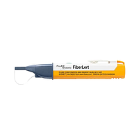
A common first step in troubleshooting is to confirm whether light is actually present on the fiber. This is useful for identifying active links before handling connectors, checking for signal presence in patch panels, and avoiding accidental work on live circuits. Devices such as the Fluke Network FIBERLERT-125 Fiber Light Detector are designed for this type of quick verification.
Based on the available product data, this model supports wavelength detection from 850 nm to 1625 nm and indicates detected optical power with a visible LED response. In field maintenance, that kind of immediate feedback is valuable because it helps technicians make a fast go/no-go assessment without setting up a more complex measurement sequence.
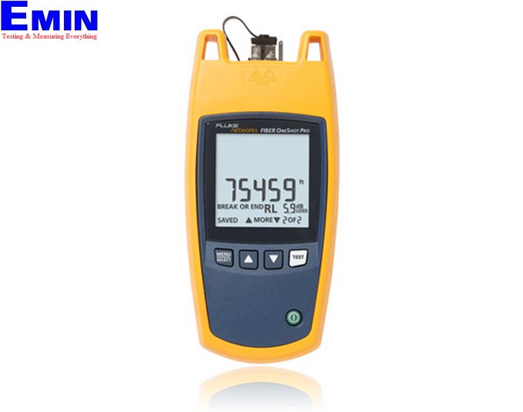
For cable routes that may have a localized break or severe loss, this type of tool is often part of the initial fault-check process. If deeper pinpointing is required afterward, teams may also review options in the optical fault locator range depending on the workflow.
Connector inspection as part of fault isolation
Many fiber issues are not caused by a broken cable at all. Dust, oil, scratches, or wear on the connector face can create reflection and insertion loss that is difficult to detect visually without dedicated inspection equipment. That is why fiber inspection is an important part of maintaining stable optical performance.
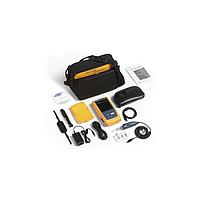
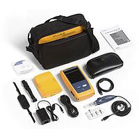
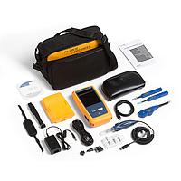
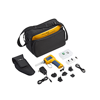
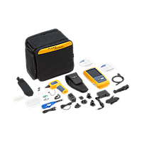
Several products in this category are oriented toward connector imaging and inspection, including the Fluke Network FI2-7000 FiberInspector Pro V2, the FI2-7000-MPO variants, and the FI-3000 FiberInspector Ultra Camera kits. These tools are relevant when technicians need to inspect LC, FC, SC, or MPO-style connector interfaces before cleaning, reconnecting, or replacing components.
The MPO-capable versions are particularly useful in higher-density environments where multi-fiber connectivity is involved. In these installations, identifying contamination across multiple fiber positions quickly can save significant service time compared with repeated manual trial and error.
Representative Fluke Network solutions in this category
Fluke Network is the main manufacturer represented here, with products covering both light detection and connector inspection workflows. This makes the category relevant for users who want a more consistent tool ecosystem for field diagnostics, especially when moving between basic checks and visual inspection tasks.
Examples include the FIBERLERT-125 for optical signal presence detection, the FI2-7000 and FI2-7000-NW FiberInspector Pro V2 kits for connector inspection, and the FI2-7300 or FI-3000 series for advanced end-face imaging. Some kits also include MPO probe support, tip sets, carrying accessories, and versions with or without integrated Wi-Fi, which can matter depending on plant policy and documentation needs.
These products should not be viewed as interchangeable. A light detector helps confirm active optical presence, while a FiberInspector solution addresses the condition of the connector interface itself. In many service scenarios, both functions are needed to reach a reliable diagnosis.
How to choose the right tool for the job
The best starting point is the actual maintenance objective. If the main concern is whether a port or patch cord is live, a compact light detection device is usually the fastest option. If repeated signal degradation occurs at connectors, especially after moves, adds, and changes, inspection equipment with the correct adapter tips becomes more relevant.
It is also worth considering connector type, access conditions, and whether the site includes single-fiber or MPO connectivity. For example, standard connector inspection may be sufficient in small camera networks, while high-density data environments often require broader inspection capability. Where damaged fibers must be repaired after diagnosis, users may also need a fusion splicer as part of the overall maintenance process.
Workflow compatibility matters as well. Some technicians prefer standalone field tools for rapid checks, while others need kits that fit into a broader documentation or certification routine. Choosing based on task frequency and connector mix will usually produce better results than choosing only by product bundle size.
Applications across field maintenance and B2B environments
This category is relevant across many professional settings: CCTV backbones in buildings, enterprise fiber cabling, industrial communication links, telecom distribution points, and campus infrastructure. In all of these cases, downtime may be caused by issues that are small in physical scale but critical in impact.
Preventive inspection is also an important use case. Routine checking of connector cleanliness and signal presence can help identify problems before they escalate into service interruptions. For facilities that depend on continuous monitoring or stable network connectivity, these tools support a more controlled maintenance strategy instead of purely reactive repair.
Final considerations
Choosing from the Fiber ranger category is less about buying a generic fiber tool and more about matching the tool to the maintenance step that actually solves the problem. Signal detection, connector inspection, and targeted troubleshooting each play a different role in restoring optical link performance.
If your work involves unstable fiber channels, connector-related loss, or recurring service calls on optical infrastructure, this category provides practical options to support faster diagnosis and more accurate field decisions. Reviewing the connector types, network density, and troubleshooting workflow at your site will help narrow the most suitable solution.
Get exclusive volume discounts, bulk pricing updates, and new product alerts delivered directly to your inbox.
By subscribing, you agree to our Terms of Service and Privacy Policy.
Direct access to our certified experts