Fusion Splicer
Which Device Is Suitable for Splicing Optical Fibers at Present
Splicing optical fibers using a fusion splicer is a solution that allows two fiber ends to be connected stably with low insertion loss. As the demand for deployment, maintenance, and troubleshooting in FTTx, LAN, METRO, CCTV systems, along with backbone and xWDM transmission networks, continues to grow, fiber splicing technology has become a suitable choice for extending cable lines or repairing breaks. The content below will present the fiber splicing process in each key stage, helping you understand how to create high-quality splices and providing enough basic information to consider choosing a splicer that meets the installation and repair needs of telecom operators and SMEs.
What Is Fiber Splicing Using a Fusion Splicer
For those who are not familiar, fiber splicing is the process of joining two fiber ends together using an electric arc generated by a fusion splicer. The fiber ends must be trimmed neatly and evenly so that light can pass through the splice efficiently, without scattering or back-reflection.
When creating a splice, the fiber must be protected to ensure durability during use. Heat shrink tubes are commonly used to reinforce the splice and surrounding fiber, increasing tensile strength and reducing environmental impact.
The fusion splicing process consists of three main stages, and understanding each step explains why this method is widely applied when a stable splice with reliable transmission performance is required.
Steps for Splicing Optical Fibers Using a Fusion Splicer
Step 1: Prepare and Precisely Cleave the Fiber
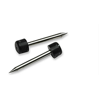
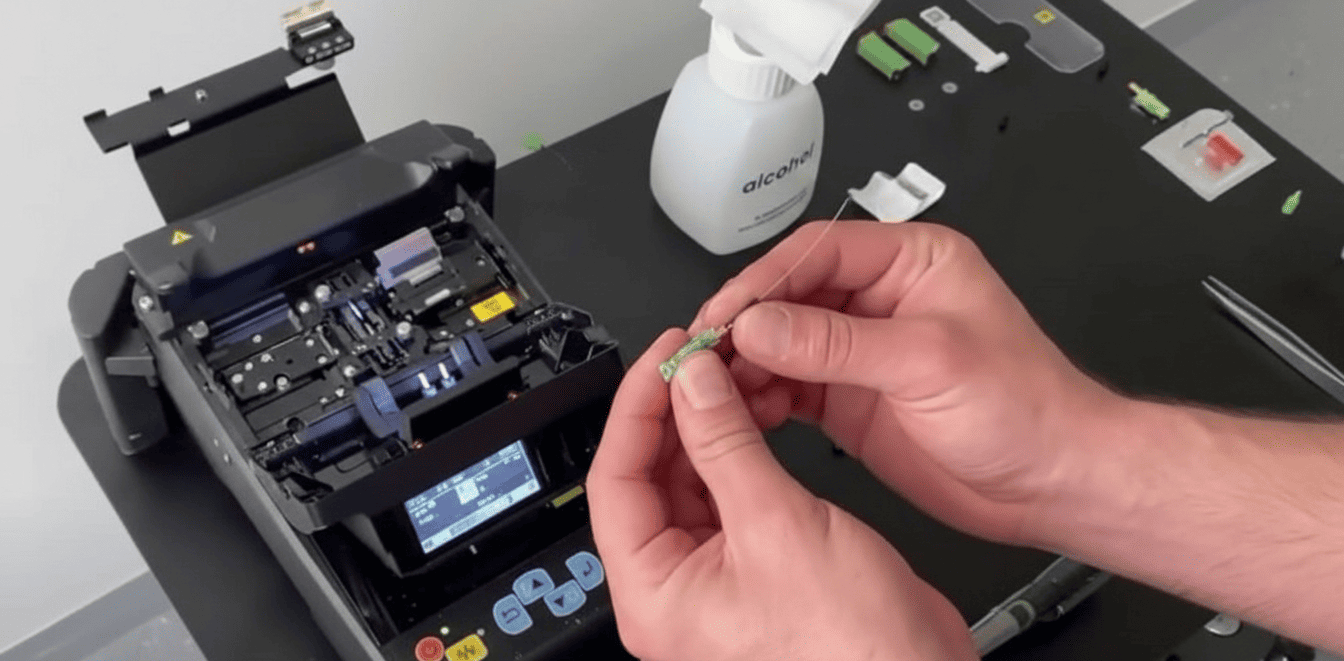
The first stage is to prepare the fiber for splicing. The bare fiber must be cleaned and carefully handled before being placed in the splicer. Begin by removing the outer jacket of the cable to expose the fibers inside without affecting the individual cores. After peeling off the outer protective layer, strip the polymer coating from each fiber using a fiber stripper.
Once the fiber cores are exposed, use a lint-free cloth with alcohol to remove dust and oil from the surface. The next step is to cleave the fiber with a specialized fiber cleaver to create a flat and even end face, ensuring a high-quality splice when placed in the splicer.
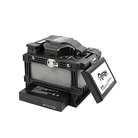
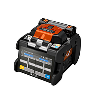
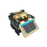
Step 2: Perform Splicing with the Fusion Splicer
The prepared fibers are placed into the splicing grooves of the machine. After alignment, initiate the splicing process using the device controls. The splicer will align the fiber cores and generate an electric arc to join them. The estimated insertion loss is displayed on the screen, allowing you to monitor the splice quality on-site.
Once the fibers form a complete transmission path, the splice must be protected. A heat shrink tube with steel reinforcement is placed around the splice to enhance durability in practical use. The tube is then heated in the splicer’s heating unit to complete the protection step.
Step 3: Inspect the Transmission Path After Splicing
Technicians can use a visual fault locator (VFL) to check continuity or an optical power meter and light source to evaluate post-splice loss. This final step confirms that the transmission path meets requirements before the cable is enclosed or the line is put into operation.
Some Notes When Using a Fusion Splicer
When planning to invest in a fusion splicer, it is important to clearly determine usage frequency to avoid unnecessary expenses. Accompanying tools such as precision fiber cleavers, strippers, and splicing kits should also be included in the total budget.
Depending on actual needs, you can choose one of two approaches:
Infrequent Use
If only a few splices are needed per month, for example in LAN rerouting projects or adding CCTV branches, renting equipment may be considered. This reduces initial investment costs while still meeting occasional tasks.
Frequent Use
If you are a service provider for Internet, FTTx, GPON, or a technical team responsible for subscriber fiber installation, owning a splicer is more reasonable. A high-quality splicer reduces troubleshooting time, ensures standard-compliant splices, and improves construction efficiency.
The effectiveness of the splice still depends significantly on the technician’s skill, combined with supporting equipment such as precision cleavers, fiber strippers, and specialized splicing kits. The more optimized the tools, the easier it is to achieve low insertion loss.
Additionally, you may refer to related optical equipment content:
Criteria for choosing an optical power meter for those unfamiliar
Measuring fiber breaks in surveillance camera systems
What is an OTDR? Key features of this type of device
Why do optical loss measurements differ between lab and field environments?
Optical Spectrum Analyzer (OSA) device solutions
Device Selection Based on Job Types
1. Backbone or xWDM Network Installation
You should prioritize core-alignment splicers, often from Japanese brands such as Fujikura or Sumitomo, distributed by EMIN. These splicers are suitable for tasks that require high stability.
2. FTTx, LAN, CCTV Installation
For home, business, or surveillance camera projects, core-to-cladding alignment splicers from mid-range brands such as Comway, INNO, or Shineway can be chosen. These models are more affordable and provide reliable splices for subscriber networks.
When working at an ODF cabinet or fiber distribution box, ensure a stable workspace and properly manage fibers in splice trays. Pay special attention to maintaining the fiber bend radius within allowed limits to avoid increased loss after the line goes into service.
Get exclusive volume discounts, bulk pricing updates, and new product alerts delivered directly to your inbox.
By subscribing, you agree to our Terms of Service and Privacy Policy.
Direct access to our certified experts