Đăng ký nhận chiết khấu độc quyền, cập nhật giá sỉ và tin sản phẩm mới nhất ngay tại hộp thư của bạn.
Bằng cách đăng ký, bạn đồng ý với Điều khoản dịch vụ và Chính sách bảo mật của chúng tôi.
Kết nối trực tiếp với đội ngũ chuyên gia của chúng tôi
Đăng ký nhận chiết khấu độc quyền, cập nhật giá sỉ và tin sản phẩm mới nhất ngay tại hộp thư của bạn.
Bằng cách đăng ký, bạn đồng ý với Điều khoản dịch vụ và Chính sách bảo mật của chúng tôi.
Kết nối trực tiếp với đội ngũ chuyên gia của chúng tôi
-Đo điện áp nhiễu DC + AC (UST):
Đo giới hạn sai số: phương pháp Chỉnh lưu toàn sóng
Phạm vi đo: 1 V đến 50 V
Dải tần số DC/AC: hình sin 45 Hz đến 400 Hz
Độ chính xác: ±(5% của rdg + 5 chữ số)
Trình tự đo: Khoảng. 4 lần đo/giây
Điện trở trong: Xấp xỉ. 1.5MΩ
Tối đa. quá tải: Urms = 250 V
-Đo tần số nhiễu (F):
Giới hạn sai số đo: phương pháp: Đo chu kỳ dao động của điện áp nhiễu
Dải đo 6.0 Hz đến 400 Hz
Dải hiển thị 16.0 Hz đến 299.9 Hz đến 999 Hz
Độ phân giải 0.1 Hz đến 1 Hz
Phạm vi 1 V đến 50 V
Độ chính xác ±(1% của rdg + 2 chữ số)
- Điện trở nối đất (RE):
Phương pháp đo Đo dòng điện và điện áp bằng đầu dò theo tiêu chuẩn IEC61557-5
Điện áp mạch hở 20/48 V, AC
Dòng điện ngắn mạch 250 mA AC
Tần số đo 94, 105, 111, 128 Hz được chọn thủ công hoặc tự động. (AFC) 55 Hz ở chức năng R1
Loại bỏ tiếng ồn 120 dB (16 2/3, 50, 60, 400 Hz)
Tối đa. quá tải Urms = 250 V
-Thông số kỹ thuật đo điện:
Dải đo 0.020 Ω đến 300 kΩ
Độ chính xác ±(2% của rdg + 2 chữ số)
sai số vận hành ±(5% của rdg + 5 chữ số)
-Tự động chuyển đổi độ phân giải đo phụ thuộc vào điện trở đất phụ RH:
RH có Umeas = 48 V: < 300 Ω, < 6 Ω, < 60 Ω, < 600 Ω
RH có Umeas = 20 V: < 250 Ω. <2,5kΩ, <25kΩ, <250kΩ
-Đo chọn lọc điện trở nối đất (Kẹp RE):
Dải đo 0.020 Ω đến 300 kΩ
-Đo điện trở (R~):
Dải đo 0.020 Ω đến 300 kΩ
-Đo điện trở (R DC):
Dải đo 0.020 Ω đến 300 kΩ
-Bù điện trở chì (RK):
Có thể bật bù điện trở dây dẫn (RK) trong các chức năng RE 3 cực, RE 4 cực (kẹp), R AC và R DC 2 cực
- Đo vòng lặp mặt đất không cọc (Hai kẹp không cọc)
Dải đo 0.02 Ω đến 199.9 Ω
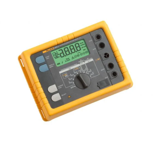
Bao gồm:
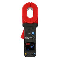
Máy kiểm tra điện trở đất 1625-2
Hướng dẫn sử dụng
Pin
Hướng dẫn sử dụng nhanh
Cáp USB
Lựa chọn mua thêm:
EI-1625: Bộ 2 kìm kẹp dòng đo điện trở đất cho 1625-2
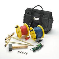
ES-162P3-2: 1 cuộn dây 25m và 1 cuộn dây 50m dùng cho FLUKE-1623-2/1625-2
ES-162P4-2: 1 cuộn dây 50m và 2 cuộn dây 25m dùng cho FLUKE-1623-2/1625-2
Datasheet
Manual
The Fluke 1625-2 earth ground tester measures earth ground loop resistances using only clamps, only stakes, or one clamp and stakes. With the stakeless test method, the Fluke 1625-2 is able to measure earth ground loop resistances for multi-grounded systems using only current clamps. This technique eliminates the dangerous, and time consuming job of disconnecting parallel grounds, and finding suitable locations for auxiliary ground stakes. This allows you to perform earth ground tests in places you’ve not considered before, such as inside buildings, on power pylons, or anywhere you don’t have access to soil.
If a bonded earth ground system does not exist for the building or structure under test, and there is only one path to ground, you can use the 1625-2 to perform the fall-of-potential test method with stakes.
The 1625-2 Earth Ground Tester offers other advanced features including:
The 1625-2 is also very easy to use. World class accessories speed set up and test time. And the tester tells you which stakes or clamps to connect for each test. The large rotary switch and buttons are easy to operate even with a gloved hand. And you can store up to 1500 records and access them easily via the USB port.
| General Specifications | ||||
| Memory | Internal memory storage up to 1500 records accessible via USB port | |||
| Measuring function | Interference voltage and frequency, earthing resistance 3- and 4-pole with/without clip-on current transformer, resistance 2-pole with AC, 2- and 4-pole with DC | |||
| Display | 4 digit (2999 Digit) - 7 segment liquid crystal display, with improved visibility | |||
| Operation | Central rotary switch and function keys | |||
| Temperature Range | ||||
| Operating temperature | -10°C to 50°C (14°F to 122°F) | |||
| Storage temperature | -30°C to 60°C (-22°F to 140°F) | |||
| Temperature coefficient | ±0.1% of reading/°C < 18°C > 28°C | |||
| Type of protection | IP56 for case, IP40 for battery door according to EN60529 | |||
| Max voltage | Warning – socket "clamp" to socket E, ES, S or H | |||
| Urms = 0 V | ||||
| Sockets E, ES, S or H to each other in any combination, max. Urms = 250 V (pertains to misuse) | ||||
| Safety | Protection by double and/or reinforced insulation. Max. 50 V to earth per IEC61010-1. Pollution degree 2 | |||
| Quality standard | Developed, designed and manufactured to comply with DIN ISO 9001 | |||
| External field influence | Complies with DIN 43780 (8/76) | |||
| Auxiliary power | 6 x 1.5 V alkaline (IEC LR6 or type AA) | |||
| Battery life span | With IEC LR6/type AA: typ. 3,000 measurements (RE+RH ≤ 1 kΩ) | |||
| With IEC LR6/type AA: typ. 6,000 measurements (RE + RH > 10 kΩ) | ||||
| Dimensions (W x H x D) | 250 x 133 x 187 mm (9.75 x 5.25 x 7.35 in) | |||
| Weight | ≤ 1.1 kg (2.43 lb) without accessories 7.6 kg (16.8 lb) incl. accessories and batteries in carrying case | |||
| Case material | Polyester | |||
| Measurement of Interference Voltage DC + AC (UST) | ||||
| Measuring limits of error: method | Full wave rectification | |||
| Measuring range | 1 V to 50 V | |||
| Display range | 0.0 V to 50 V | |||
| Resolution | 0.1 V | |||
| Frequency range | DC/AC 45 Hz to 400 Hz sine | |||
| Accuracy | ±(5% of rdg + 5 digit) | |||
| Measuring sequence | Approx. 4 measurements/s | |||
| Internal resistance | Approx. 1.5 MΩ | |||
| Max. overload | Urms = 250 V | |||
| Measurement of Interference Frequency (F) | ||||
| Measuring limits of error: method | Measurement of oscillation period of the interference voltage | |||
| Measuring range | 6.0 Hz to 400 Hz | |||
| Display range | 16.0 Hz to 299.9 Hz to 999 Hz | |||
| Resolution | 0.1 Hz to 1 Hz | |||
| Range | 1 V to 50 V | |||
| Accuracy | ±(1% of rdg + 2 digit) | |||
| Earthing Resistance (RE) | ||||
| Measuring method | Current and voltage measurement with probe as IEC61557-5 | |||
| Open circuit voltage | 20/48 V, AC | |||
| Short circuit current | 250 mA AC | |||
| Measuring frequency | 94, 105, 111, 128 Hz selected manually or automatic. (AFC) 55 Hz in function R1 | |||
| Noise rejection | 120 dB (16 2/3 , 50 , 60, 400 Hz) | |||
| Max. overload | Urms = 250 V | |||
| Electrical Measurement Specifications | ||||
| Intrinsic Error or Influence Quantity | Reference Conditions or Specified Operating Range | Designation Code | Requirements or Test in Accordance with the Relevant Parts of IEC 1557 | Type of Test |
| Intrinsic error | Reference conditions | A | Part 5, 6.1 | R |
| Position | Reference position ±90° | E1 | Part 1, 4.2 | R |
| Supply voltage | At the limits stated by the manufacturer | E2 | Part 1, 4.2, 4.3 | R |
| Temperature | 0°C and 35°C | E3 | Part 1, 4.2 | T |
| Series interference voltage | See 4.2 and 4.3 | E4 | Part 5, 4.2, 4.3 | T |
| Resistance of the probes and auxiliary earth electrodes | 0 to 100 x RA but ≤ 50 kΩ | E5 | Part 5, 4.3 | T |
| System frequency | 99% to 101% of the nominal frequency | E7 | Part 5, 4.3 | T |
| System voltage | 85% to 110% of the nominal voltage | E8 | Part 5, 4.3 | T |
| Operating error | B = ±(|A| + 1,15 √E21 E22 E23 E24 E25 E26 ) | Part 5, 4.3 | R | |
| B[%] = ± B/fiducial value x 100% A = intrinsic error En = variations R = routine test T = type test | ||||
| Measuring range | 0.020 Ω to 300 kΩ | |||
| Display range | 0.001 Ω to 2.999 Ω | |||
| 3.00 Ω to 29.99 Ω | ||||
| 30.0 Ω to 299.9 Ω | ||||
| 0.300 kΩ to 2.999 kΩ | ||||
| 3.00 kΩ to 29.99 kΩ | ||||
| 30.0 kΩ to 299.9 kΩ | ||||
| Resolution | 0.001 Ω | |||
| 0.01 Ω | ||||
| 0.1 Ω | ||||
| 1 Ω | ||||
| 10 Ω | ||||
| 100 Ω | ||||
| Accuracy | ±(2% of rdg + 2 digit) | |||
| Operating error | ±(5% of rdg + 5 digit) | |||
| Measuring time | Typical 8 seconds with a fixed frequency 30 sec. max. with AFC and complete cycle of all measuring frequencies | |||
| Additional error because of probe-and auxiliary earth electrode resistance | RH(RS + 2000 Ω)/RE x 1.25 x 10⁻⁶% + 5 digits | |||
| Measuring error of RH and RS | Typ. 10% of RE + RS + RH | |||
| Max. probe resistance | ≤ 1 MΩ | |||
| Max. auxiliary earth electrode resistance | ≤ 1 MΩ | |||
Automatic check if error is kept within the limits required by IEC61557-5. | ||||
| Automatic Switchover of Measuring Resolution in Dependence to Auxiliary Earth Electrode Resistance RH | ||||
| RH with Umeas = 48 V | < 300 Ω | |||
| < 6 Ω | ||||
| < 60 Ω | ||||
| < 600 Ω | ||||
| RH with Umeas = 20 V | < 250 Ω | |||
| < 2.5 kΩ | ||||
| < 25 kΩ | ||||
| < 250 kΩ | ||||
| Resolution | 1 mΩ | |||
| 10 mΩ | ||||
| 100 mΩ | ||||
| 1 Ω | ||||
| Selective Measurement of the Earthing Resistance (RE Clamp) | ||||
| Measuring method | Current and voltage measurement with probe as per EN61557-5 and current measurement in the individual branch with additional current transformer (patent applied for). | |||
| Open circuit voltage | 20/48 V AC | |||
| Short circuit current | 250 mA AC | |||
| Measuring frequency | 94, 105, 111, 128 Hz selected manually or automatically (AFC), 55 Hz (R1) | |||
| Noise rejection | 120 dB (162/3, 50, 60, 400 Hz) | |||
| Max. overload | Max. Urms = 250 V (measurement will not be started) | |||
| Measuring range | 0.020 Ω to 300 kΩ | |||
| Display range | 0.001 Ω to 2.999 Ω | |||
| 3.00 Ω to 29.99 Ω | ||||
| 30.0 Ω to 299.9 Ω | ||||
| 0.300 kΩ to 2.999 kΩ | ||||
| 3.00 kΩ to 29.99 kΩ | ||||
| Resolution | 0.001 Ω | |||
| 0.01 Ω | ||||
| 0.1 Ω | ||||
| 1 Ω | ||||
| 10 Ω | ||||
| Accuracy | ±(7% of rdg + 2 digit) | |||
| Operating error | ±(10% of rdg + 5 digit) | |||
| Additional error because of probe- and auxiliary earth typ. electrode resistance | RH(RS + 2000 Ω)/RETOTAL x 1.25 x 10⁻⁶% + 5 digits | |||
| Measuring error of RH and RS | Typ. of 10% of RETOTAL + RS + RH | |||
| Measuring time | Typ. 8 sec. with a fixed frequency 30 sec. max. with AFC and complete cycle of all measuring frequencies. | |||
| Minimal current in single branch to be measured | 0.5 mA | With transformer (1000:1) | ||
| 0.1 mA | With transformer (200:1) | |||
| Max. interference current through transformer | 3 A | With transformer (1000:1) | ||
| 1. With recommended current clamps/transformers. | ||||
| Resistance Measurement (R~) | ||||
| Measuring method | Current and voltage measurement | |||
| Measuring voltage | 20 V AC, square pulse | |||
| Short circuit current | > 250 mA AC | |||
| Measuring frequency | 94, 105, 111, 128 Hz selected manually or automatically (AFC) | |||
| Measuring range | 0.020 Ω to 300 kΩ | |||
| Display range | 0.001 Ω to 2.999 Ω | |||
| 3.00 Ω to 29.99 Ω | ||||
| 30.0 Ω to 299.9 Ω | ||||
| 300 Ω to 2999 Ω | ||||
| 3.00 kΩ to 29.99 kΩ | ||||
| 30.0 kΩ to 299.9 kΩ | ||||
| Resolution | 0.001 Ω | |||
| 0.01 Ω | ||||
| 0.1 Ω | ||||
| 1 Ω | ||||
| 10 Ω | ||||
| 100 Ω | ||||
| Accuracy | ±(2% of rdg + 2 digit) | |||
| Operating error | ±(5% of rdg + 5 digit) | |||
| Measuring time | Typical 6 seconds | |||
| Max. interference voltage | 24 V, with higher voltages measurement will not be started | |||
| Max overload | Urms max. = 250 V | |||
| Resistance Measurement (R DC) | ||||
| Measuring method | Current- voltage measurement as per IEC61557-4 possible | |||
| Measuring voltage | 20 V DC | |||
| Short circuit current | 250 mA DC | |||
| Formation of measured value | With 4-pole measurement wires on H, S, ES can be extended without additional error. Resistances > 1 Ω in wire E can cause additional error of 5m Ω/Ω. | |||
| Measuring range | 0.020 Ω to 300 kΩ | |||
| Display range | 0.001 Ω to 2.999 Ω | |||
| 3.00 Ω to 29.99 Ω | ||||
| 30.0 Ω to 299.9 Ω | ||||
| 300 Ω to 2999 Ω | ||||
| 3.0 kΩ to 29.99 kΩ | ||||
| 30.0 kΩ to 299.9 kΩ | ||||
| Resolution | 0.001 Ω | |||
| 0.01 Ω | ||||
| 0.1 Ω | ||||
| 1 Ω | ||||
| 10 Ω | ||||
| 100 Ω | ||||
| Accuracy | ±(2% of rdg + 2 digit) | |||
| Operating error | ±(5% of rdg + 5 digit) | |||
| Measuring sequence | Approx. 2 measurements/s | |||
| Measuring time | Typical 4 second including reversal of polarity (2-pole or 4-pole) | |||
| Maximum interference voltage | ≤ 3 V AC or DC, with higher voltages measurement will not be started | |||
| Maximum inductivity | 2 Henry | |||
| Maximum overload | Urms = 250 V | |||
| Compensation of Lead Resistance (RK) | ||||
| Compensation of lead resistance (RK) can be switched on in functions RE 3-pole, RE 4-pole (clamp), R AC, and R DC 2-pole | ||||
| Formation of measured value | Rdisplay = Rmeasured - Rcompensated2 | |||
| 2. Value of setpoint entry RK = 0.000 Ω, variable from 0.000 to 29.99 Ω by means of measuring adjustment. | ||||
| Stakeless Ground Loop Measurement (Two Clamp Stakeless) | ||||
| Switch position | RA 4-pole (two clamp Stakeless) | |||
| Resolution | 0.001 Ω to 0.1 Ω | |||
| Measuring range | 0.02 Ω to 199.9 Ω | |||
| Accuracy | ±(7% rdg + 3 digit) | |||
| Operating error | ±(10% rdg + 5 digit) | |||
| Measuring voltage | Vm = 48 V AC (primary) | |||
| Measuring frequency | 128 Hz | |||
| Noise current (IEXT) | Max. IEXT = 10 A (AC) (RA < 20 Ω) | |||
| Max. IEXT = 2 A (AC) (RA > 20 Ω) | ||||
| Measuring principle: Stakeless measurement of resistance in closed loops using two current transformers. Automatic range selection. The information regarding stakeless ground loop measurements is only valid when used in conjunction with the recommended current clamps at the minimum distance specified. | ||||