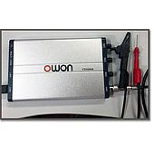
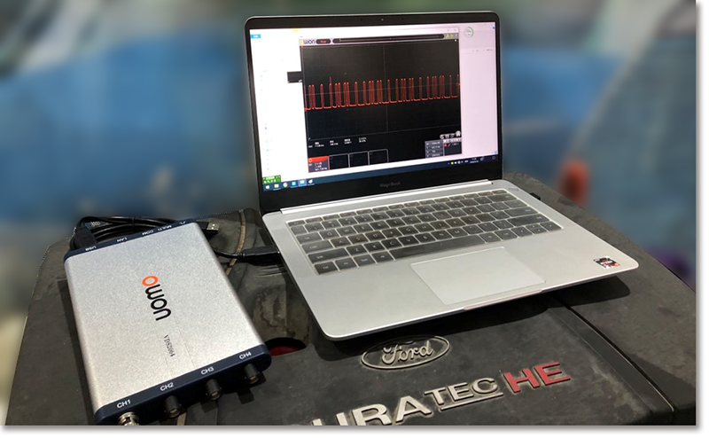
Crankshaft position sensor oscilloscope testing gives automotive technicians a direct way to observe signal behavior that may not be visible through a basic voltage check. In the example described here, an OWON VDS2064 PC oscilloscope and a notebook computer are used to examine the waveform produced by a magnetoelectric crankshaft position sensor.
The resulting waveform can help technicians investigate engine speed changes, mechanical irregularities, and incorrect sensor terminal connections. It should be evaluated together with the vehicle circuit diagram, operating symptoms, and appropriate mechanical checks rather than treated as a diagnosis on its own.
How a magnetoelectric crankshaft sensor produces a signal
A magnetoelectric crankshaft position sensor can generate its own signal without an additional power supply. As the metal wheel rotates, it changes the magnetic field around the sensor. This changing field produces a corresponding voltage in the circuit.
The waveform amplitude is not necessarily constant. According to the application example, amplitude increases as engine speed rises. Variations may also reflect changes associated with the engine's intake, compression, power, and exhaust stages. Viewing these details with an oscilloscope can therefore provide useful evidence about both sensor output and mechanical operation.
Basic test setup with the OWON VDS2064
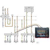
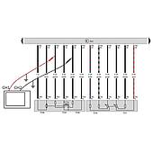
The test setup consists of a notebook computer, the OWON VDS2064 digital oscilloscope, its PC software, and the required test leads. After installing and opening the software, connect the oscilloscope and probe the sensor circuit according to the relevant wiring information.
Before interpreting the trace, technicians should confirm the time-base and voltage settings shown with the captured waveform. The source examples include settings of 5 ms/div and 10 V/div for one capture, followed by 10 ms/div and 10 V/div for a later comparison. Because the time base changes between these examples, waveform comparisons should take the displayed settings into account.
Using waveform changes to investigate a mechanical problem
One case involved a Weichai WP7 engine in a Zoomlion crane after an overhaul. Three months after the overhaul, the engine could not accelerate normally to 1900 rpm. When the pressure relief valve opened at that speed, engine speed fell to 1500 rpm.
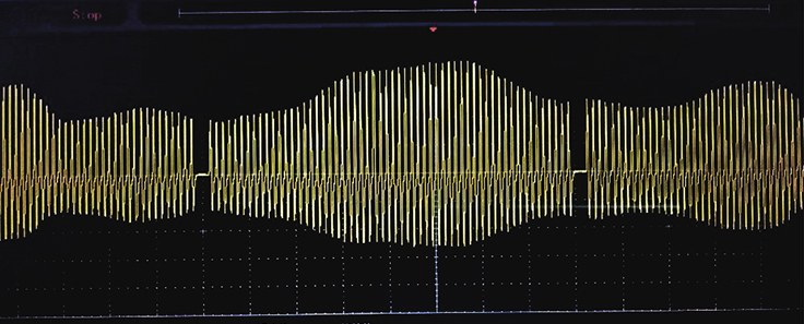
The first crankshaft sensor waveform was recorded at 5 ms/div and 10 V/div. Four months later, the engine's maximum speed had fallen to 1500 rpm. A second measurement made with the OWON VDS2064 showed that the differences in waveform amplitude had become more pronounced.
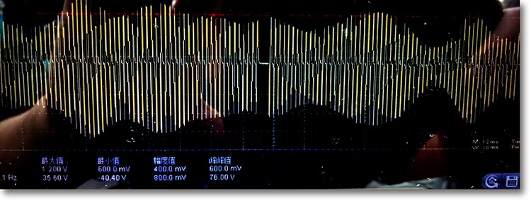
Further investigation considered abnormal forward-and-backward or vertical crankshaft movement. A mechanical check at the front crankshaft pulley found very little movement clearance, while the case assessment identified excessive upper and lower crankshaft runout associated with a bearing-related mechanical condition. The example demonstrates how an electrical waveform can direct attention toward a mechanical inspection, even though the trace alone does not establish the root cause.
Observing cylinder contribution through crankshaft speed
Crankshaft sensor waveforms may also support an indirect assessment of cylinder contribution. If a cylinder does not produce power when expected, crankshaft speed may decrease during that part of the operating cycle. The resulting variation can appear in the crankshaft position sensor waveform.
This approach may provide useful diagnostic direction without immediately measuring primary and secondary ignition waveforms. However, the waveform should be interpreted carefully because an irregular pattern can have more than one possible cause. Comparing repeated captures under consistent operating conditions makes the analysis more meaningful.
Why sensor terminal polarity matters
The two terminals of a magnetoelectric crankshaft position sensor are not interchangeable from the ECU's perspective. Reversing them changes the signal relationship. In the source example, the reversed connection produced a difference described as approximately “half a tooth” compared with the normal connection.
That change may create a timing error or cause the ECU to interpret the timing as incorrect. A comparison performed on a Great Wall Fengjun 6 pickup showed distinct normal and reversed-terminal waveforms. Technicians should therefore verify terminal identification against the circuit diagram instead of assuming that either connection will produce an equivalent signal.
Interpreting crankshaft waveforms effectively
A sound analysis begins with a stable connection and a clearly displayed trace. Record the engine condition, rotational speed, time-base setting, and voltage scale for each capture. When comparing measurements taken at different times, account for any changes in scope settings or operating conditions.
Look for changes in amplitude, spacing, and overall waveform consistency. A growing amplitude difference may justify further investigation, but it should be correlated with symptoms and mechanical inspection. If polarity is in question, compare the measured pattern with the expected circuit connection before changing components.
The computer display used by the OWON VDS2064 makes waveform details easier to review during automotive maintenance. PC-based operation also provides a compact setup that can be carried to the vehicle.
OWON VDS Series features relevant to automotive work
The OWON VDS Series is presented as a portable PC oscilloscope range for technicians who need both mobility and practical measurement functions. The listed series capabilities include bandwidth up to 100 MHz, a maximum real-time sample rate of 1 GS/s, and a 10M record length.
The software interface supports FFT, X-Y display, and two waveform views on the same screen. Trigger options include edge, video, slope, pulse, and alternate triggering. The series information also lists USB isolation to reduce signal interference and provide additional PC protection, USB bus power, and optional LAN remote control. Its ultra-thin body is intended to make transport and field use easier.
For automotive sensor work, the main value of the oscilloscope is the ability to turn a rapidly changing electrical signal into a visible waveform. When used with correct wiring information and systematic mechanical checks, the OWON VDS2064 can help technicians investigate crankshaft sensor operation, terminal polarity, engine speed variation, and potential mechanical irregularities.