For full functionality of this site it is necessary to enable JavaScript.

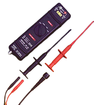
Que đo vi sai Pintek DP-25 ( 1.3KVp-p / 25MHz Economic Model )

3 RANGE ATTENUATOR.
1000V INPUT CAT III
LOW BATT. AUTO OFF.
SEPARATING DESIGN.CONVENIENT, DURABLE.
MEET CE, IEC 1010, EN 61010, UL 3111.
Chi tiết

More Spec     DM-1    DM-2    Manual    Differential Probe Selection Guide

Band width (-3dB, 50Ω load): DC-25MHz . ( x 20: DC~15MHz)
Accuracy :
± 2% at 20-30℃ 70% RH after 20 minutes warm up.
Attenuation :
x 20, x 50, x 200 ( Into 1MΩ scope ) ; x 40, x 10
, x 400 ( Into 50Ω load )

Maximum operation Voltage ( DC + peak AC ) :

≦ ± 140V at x 20
≦ ± 350V at x 50
≦ ± 1300V at x 200

Maximum input Differential Voltage :
1300V ( DC + peak AC ) or 1000V RMS
Maximum input Voltage to Ground :
1000V ( DC + peak AC ) or 600V RMS
Common Mode Rejection Ratio ( CMRR ):

60Hz : >10,000 : 1
100Hz: >1,000 : 1
1MHz: > 300 : 1

Noise :
≦ 2 mV rms ( Into 50Ω load )
Input Impedance :

2MΩ, 2.3 PF between inputs and ground.
4MΩ, 1.2 PF between inputs.

Power :
external 6V-9V DC.

WARNING

  1. Do not use DP-25 above 1000v ( DC + peak AC ) between ground and the input or 1,300V ( DC + peak AC ) between the input lead.
  2. Do not operate DP-25 in wet or damp condition.
  3. Do not operate DP-25 in an explosive atmosphere.
  4. Do not immerse DP-25 in liquids.
  5. Do not operated DP-25 without covers.
  6. Please change the battery when the "LOW BATT " LED is lighted. At this time DP-25 can operate but not guaranteed the accuracy.
  7. DP-25 can not operate if both POWER and LOW BATT LED are not light.

FEATURES

  1. The DP-25 FET input differential probe provieds a safe means of measuring circuits with floating potentials up to 1000 V ( DC+ peak AC ) from ground and 1300V ( DC + peak AC ) differential.
  2. The DP-25 converts the high voltage differencial input signal to a low voltage ground refereced signal for display on any Oscilloscope.
  3. The output BNC of DP-25 is calibrted to drive a high impedance ( 1MΩ ) load.

INSTRUCTION FOR USE

  1. Connect the output BNC of DP-25 to the input BNC of the Oscilloscope by the accessory BNC cable.
  2. Adjust the vertical offset of the Oscilloscope if necessary.
  3. Set the select proper range of the DP-25 and the V / DIV of the Oscilloscope according to the scale conversion chart.
  4. Scale conversion chart : The effective V / DIV is the attenuation factor of x 20, x 50, x 200 multiplied by the scale factor of the Oscilloscope. It will be twice when the 50 Ω load was used. For example, with the range set at x 200,
    and the scope set to 0.5 V / DIV, the effective V / DIV equals 200 x 0.5 or 100 V, with the 50
    Ω load was used, it becomes 200V, the power consumption will increase too.


    NOTE :
    If the voltage of the input signal exceeeds the linear range of the setting range.The signal output of the DP-25 would not accurately, the wave form display will be cut off.
  • Cam kết chất lượng
  • Bảo hành chính hãng
  • Giao hàng tận nơi
  • Đơn giản hóa giao dịch

Đăng ký nhận bản tin - cơ hội nhận khuyến mãi