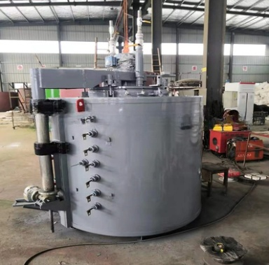
Ứng dụng
Loạt lò nitơ hóa và oxy hóa khí loại hố tiết kiệm năng lượng này là lò điện loại hoạt động định kỳ, được sử dụng để nitơ hóa khí, nitơ hóa và oxy hóa, và cacbon hóa các sản phẩm thép cacbon, thép hợp kim, gang, luyện kim bột và các vật liệu khác.
Điện áp định mức, V: 380
Công suất định mức, kw: 150±10%
Số pha: 3
Tần số, Hz: 50
Phương pháp kết nối: Có
Số vùng điều khiển nhiệt độ: 3
Nhiệt độ hoạt động tối đa, ℃: 700
Độ đồng đều của nhiệt độ lò, ℃: ± 5 (ở 650 ℃)
Độ tăng nhiệt độ của thành ngoài vỏ lò, ℃: ±45
Tổn thất điện năng của nồi hơi rỗng: 15%
Kích thước vùng làm việc, mm: Ф1000×2000
Kích thước ống dẫn khí, mm: Ф1000×2000
Kích thước lò, mm: Ф1200×2400
Kiểm soát nhiệt độ: Điều khiển tự động màn hình cảm ứng PLC
Chế độ kiểm soát nitơ: Kiểm soát nitơ tự động
Chế độ nâng nắp lò: Nâng điện tự động
Lưu thông khí nóng quạt: Động cơ kín chống ăn mòn làm mát bằng nước 3KW
Quạt làm mát: Quạt 1.5KW
Loại khí quyển: Amoniac, amoniac phân hủy, nitơ, không khí
Kiểm soát khí: Khí được kiểm soát bằng van điện từ và lưu lượng kế
Bề mặt gia nhiệt: Xung quanh thân lò
Loại vòng đệm: Vòng đệm cao su silicon
Chế độ làm mát của vòng đệm: làm mát bằng nước
Bơm chân không (khử oxy, giảm thời gian thanh lọc và tiêu thụ nitơ và amoniac): Bơm chân không 2X-70
Tải trọng, kg
Vật liệu lò: Thép không gỉ 310S dày 10mmm
Vật liệu tấm chắn gió dưới của nắp lò: Thép không gỉ 310S dày 6mm
Vật liệu ống dẫn khí: Thép không gỉ 310S dày 4mm
Vật liệu hộp cách nhiệt nắp lò: Thép không gỉ 310S dày 8mm
Vật liệu bộ phận gia nhiệt: Dải hợp kim chịu nhiệt độ cao 0Cr21AL6Nb
Độ chân không: -0.1mpa
2.Execution Standards
The furnace is made according to the following national standards:
2.1 Basic Technical Requirements for Industrial Electrothermal Equipment (GB 10067.1-88)
2.2 Basic Technical Conditions of Resistance Furnace (GB 10067.4-88)
2.3 Measurement Method of Effective Heating Layer of Heat Treatment Furnace (GB9452-88)
2.4 Safety of Electrothermal Equipment Part 1 General Requirements (GB5959.4-92)
2.5 Safety of Electrothermal Equipment Part 4: General Requirements for Resistance Furnaces (GB5959.4-92)
4.Using Condition
4.1 For indoor use;
4.2 There is no conductive dust, explosive gas and corrosive gas that can seriously damage metal and insulation.
4.3 There is no obvious vibration.
4.4 Environment temperature: 0℃~35℃;
4.5 relative humidity ≤95%(25℃);
4.6 elevation <2000m
4.7 Inlet Cooling water temperature ≤30℃
4.8 Compressed air: pressure 0. 4~0.6 MPa;
5.Furnace structure
The structure of the electric furnace is mainly comprised of furnace body, heating element, fan circulation mechanism, stainless steel furnace, temperature control system, nitrogen potential control system, etc. The opening and closing mode of the furnace cover is electric automatic lifting, and automatic interlock protection through the travel switch.
5.1 Furnace shell: The shell is mainly made of 12#-14# section steel and high-quality 4mm thick steel plate welded into a solid frame. The whole steel structure has the advantages of beautiful appearance, high rigidity and strength.The appearance of the furnace body is straight and beautiful without wrinkles or unevenness. The exterior of the furnace body shall be painted with two coats of primer and two coats of finishing paint according to relevant standards. The color code shall be selected according to the general industry standard or Party A's factory standard, and the key parts shall be painted with high temperature resistant paint.
5.2 Furnace lining: The lining is a compound structure. The main body is made of high-quality aluminum silicate refractory fiber folded blocks of Luyang brand, Shandong. Standard fixings and scientific and reasonable mounting methods are used. The fiber blocks are pre-compressed again before installation, and fixed on the shell with special stainless steel anchors. The total installation thickness of the furnace lining is 350mm.The structure has low thermal conductivity, low heat solubility, excellent chemical stability, thermal stability, thermal vibration resistance, excellent tensile strength and corrosion resistance. The highest temperature resistance of aluminum silicate fiber is 1260 ℃, and the material of the fixture is stainless steel round steel. After the lining body is made, the thermal efficiency of the furnace is maximized.
5.3 Heating elements:
It is made of high temperature resistant 0Cr21AL6Nb alloy.The resistance strips are fixed with special ceramic screws, which are convenient for installation, maintenance and replacement. It will never form thermal short circuit with the furnace shell and cause local overheating of the furnace shell. During installation, ceramic gaskets are used to sperate the fiber wall and the resistance strips to ensure that the fiber surface does not directly contact with the resistance strips, so as to increase the heating effect of the resistance strips.The ceramic screws and gaskets are made of corundum material and sinteredat high temperature to ensure that they have enough strength and service life.The equipment is divided into three heating areas, and the arrangement of heating elements corresponds to the setting of heating zones.
Installation of electric heating elements: With the advanced hanging structure, the radiation efficiency is high, the heat exchange in the furnace is strengthened, the thermal efficiency of the furnace is improved, and the service life of the electric heating element is prolonged.
The heating element is processed into wave structure by special molds and installed around the furnace. When the ceramic screw nails are used to install the resistance strips, the ceramic gaskets are used to separate the resistance belt from the fiber lining. The ceramic screw nails pass through the ceramic gaskets from the wave crest of the resistance strips and rotates clockwise to screw into the fiber lining. Because the ceramic nails have trapezoidal rib and has strong adhesion with the fiber, the resistance strips are firmly fixed and are easy to install.
5.4 Nitriding furnace tank
There is a stainless steel muffle tank in the furnace, and the furnace tank is made of stainless steel plate and 310S stainless steel.In order to isolate the protective atmosphere in the furnace from the outside air and keep the sealing state, the upper part of the furnace is also equipped with a water-cooled sealing device, which uses the high-temperature silicon sealing ring.
When the furnace cover is closed, it is compressed by the furnace cover pressing device, and the sealing effect is achieved by water cooling.
5.5 Air duct
In order to make the hot air blown by the fan form convection in the furnace, the furnace is equipped with an air duct. The air duct is welded by 4mm stainless steel plate (310S).
The air duct is placed in the muffle tank. The hot air blown by the fan is blown around the furnace through the wind deflector and enters the furnace bottom. After passing through the air duct from the furnace bottom, the air is introduced from the bottom to the center of the furnace and recycled to the top of the furnace. The air in the muffel tank reaches circulation convection and the furnace temperature is more uniform.
5.6 Circulating fan
In order to make the temperature in the furnace more uniform, a 3kW large flow water-cooled hot air circulation anti-corrosion fan is installed on the furnace cover, which is used to stir the air in the furnace during the heating process to form a thermal cycle in the furnace. The system consists of anti-corrosion motor, water cooling device, fan blade shaft and impeller. When in use, the operator only needs to click the control button, and the fan power supply is connected with the furnace cover. When the furnace cover rises, the power supply of the fan is cut off, and the fan stops working.
5.7 Furnace cover and cover lifting mechanism
It is comprised of a cover body, a heat insulation box, a strong convection fan, an exhaust pipe and an air inlet pipe.The external plate of the cover is A3 steel plate
with a thickness of 30mm.
The lifting of the furnace cover is completed by an electric lifting mechanism, which is provided by the power motor device.
When the furnace cover needs to be raised, just start the lifting device, the furnace cover will rise slowly. If the furnace cover needs to be lowered, just open the lowering button, the furnace cover will fall slowly. There are two limit switches at the lifting shaft.
When the lifting shaft rises, the lower limit switch automatically cuts off the power supply of the circulating fan and the heating element in the furnace to avoid the danger of improper operation. When the furnace cover rises to the specified position, the upper limit switch automatically cuts off the power supply.
5.8 Intelligent temperature control system
In order to make the temperature in the furnace reach the requirement of uniformity, the furnace is divided into 3 zones for temperature control. The main control instrument of the furnace temperature control system adopts Japanese advanced intelligent no-overshoot expert temperature controller, which is equipped with a Shimadian power trigger to control the furnace temperature. The measured value and displayed value are independent and four-digit, and the temperature control value is preset by the user.
At present, the advanced high-power thyristor is selected as the actuator, and the furnace temperature is automatically controlled by the intelligent digital display temperature controller.
The system has advanced intelligent PID control algorithm and perfect self-tuning and self-adaptive functions. The intelligent temperature controller is displayed by double four-digit LCD digital tube, and SV and PV value are displayed at the same time. Eight types of range settings can be input freely. The AC100-240V wide range power supply is adopted, so there is no need to worry about the fluctuation of power supply voltage.
The system can automatically or manually adjust the power of each zone, which can better control the furnace temperature uniformity. After manually adjusting the power, the system will automatically control the temperature according to the manually adjusted power, which is convenient for operation and accurate for temperature control.
A) Power control system:
The control and execution system adopts high-power thyristor combination unit, aluminum alloy heat dissipation and a set of air cooling system, and is equipped
with automatic circuit breaker and fast fuse for secondary protection. Each zone of the system has a large current contactor as the furnace temperature
protection unit. Once the thyristor is broken down by the current due to fault, the current can not be controlled if the large current protection contactor is not installed.
Even if the alarm device is installed, the main control power source can not be cut off. If the operator leaves, the temperature in the furnace will be out of control. After installing the large current protection contactor, once the thyristor is broken down by the current, the furnace reaches the upper limit over temperature alarm value, the contactor can cut off the main power supply at the same time of the alarm, which can reliably ensure the normal operation of the furnace and avoid the loss of the furnace after out of control.
Indication of working conditions in each zone of electric furnace:
Each phase and zone has indicator light to indicate whether it works or not. When the furnace is heated up, the indicator light will flash with the size of the current, and the staff can intuitively see the working conditions of each phase in each zone of the furnace.
Each zone and phase of the furnace temperature control system is equipped with an ammeter to display the real-time working current of the heating element.
Alarm device:
Each area of the supporting control system is equipped with the function of overtemperature sound and light alarm. As long as any area in the furnace reaches the upper limit alarm value set by the temperature, the system alarm will give an alarm, and the alarm indicator corresponding to this area will also flash. At the same time, the main power supply of the heater is cut off by the large current contactor, and the operator can directly find out the cause according to the alarm indication, so as to ensure the safe operation of the furnace.
Interlock protection function:
Each mechanical transmission part of the electric furnace adopts interlock control, that is, the heating element power is automatically cut off after the furnace cover is slightly opened, and the furnace cover is automatically stopped when it is raised to the designated position. The heater power is automatically restored when the furnace cover is closed, so as to effectively prevent misoperation and failure.
Main control cabinet:
The body of the main control cabinet of the furnace adopts the national standard GGD, and its overall dimension is 2100 *800*600mm, and the ventilation and heat dissipation effect is good. The cabinet body is coated with industrai gray. An axial flow fan is installed on the back door of each control cabinet, which can effectively reduce the temperature in the control cabinet after convection with the SCR cooling fan.
The electrical components are of are domestic famous brands.
5.9 Fast Cooling Equipment
In order to meet the cooling requirements of customers, a cooling blower is installed at the bottom of the electric furnace. The upper part of the furnace is provided with a cooling port, which is closed when the electric furnace is working. When cooling, open the cooling port and start the cooling fan, which makes the air flow in the furnace and bring out heat, so as to achieve the purpose of rapid cooling
5.10 Nitrogen process control system
5.10.1 features
A) Model: pit type furnace nitrogen potential/temperature (ammonia decomposition rate) control system.
B) process: it can be used for nitriding, soft nitriding and automatic control of nitrogen potential (ammonia decomposition rate) and temperature of process.
C) Suitable atmosphere: pure ammonia, ammonia and methanol/ethanol, CO2, etc.
D) Control mode: two ammonia decomposition control modes:
E) Under the automatic mode, the thermal conductivity hydrogen analyzer is used as the sensor, and programmable nitrogen potential controller is used to control the ammonia decomposition rate in the furnace by adjusting the ammonia flow through the solenoid valve.
F) Under the manual mode, the constant ammonia gas and the regulated ammonia gas are controlled with stable flow.
G) Process programming: nitrogen control instrument and temperature control instrument to realize the synchronous control of temperature and nitrogen potential. Each process procedure can be divided into 10 sections, and 100 sets of procedures can be stored.
Programs can be modified by users so that they can be called later.
H) Other functions of the system: the system has the functions of process time completion and ammonia potential overrun alarm.
5.10.2 Furnace temperature control
Considering the reliability, control accuracy and simple operation of the system, the temperature controller imported from Japan is used as the lower instrument, and the intelligent instrument is used for control, which can self-tune and self-adapt control each zone, so that the control accuracy of each zone can reach the best value, and the temperature control accuracy can reach ± 1 ℃.
5.10.3 PLC control
The PLC system calculates and analyzes the temperature and ammonia decomposition rate, and sends the target value of temperature and nitrogen potential to the lower system for comprehensive and unified management. According to the actual working conditions collected by the lower system, the system also displays the temperature, ammonia decomposition rate, nitrogen potential and time in the actual nitriding process.
According to the general mathematical model established by our company, the system automatically controls the whole nitriding process (temperature, nitrogen potential, time, etc.).
In actual operation, the workers only need to input the corresponding process number according to the material and technical requirements of the workpiece to be processed in each zone, and press the start button, and the whole process will be automatically controlled by the computer.
• After the operation of the process, the system will ring the bell to prompt
• the operator to operate the quick cooling and nitrogen supply. The quick
• cooling and nitrogen supply are controlled by buttons.
• the instrument is provided with power-off protection, continued operation
• after restoration of power, and alarm when the furnace is discharged,
• ammonia decomposition rate exceeds the limit and temperature exceeds the limit.
C) process control has the switching function of step and skip section.
5.10.4 Technical index:
Control precision of ammonia potential:± 3.0% + H2;
Control range of ammonia decomposition rate: 0% ~ 100%;
Furnace temperature control accuracy: ± 1 ℃;
5.11 Steam generator
5.11.1 Technical parameters
Rated power: 9KW,
Rated evaporation capacity: 25KG/H;
Rated steam temperature: 171℃;
Working voltage:380V;
Water volume: 28L;
Weight:75KG;
Overall dimension:77*51*92cm;
Power supply: 3 phase, 380V, 50Hz;
Main steam diameter (DN): 15;
Safety valve diameter (DN): 15;
Inlet diameter (DN): 15;
5.11.2 Design and structure of steam generator
A) Conform to Chinese steam generator standard
B) Low water level shutdown alarm
C) Over current stop alarm
5.11.3 Main electrical appliances and control system of steam generator:
A) The main electric heater shall be a joint venture product.
B) The components of the main electric control cabinet are well-known brands in China
C) Pressure limiting automatic control device
D) Automatic relief valve discharge device
E) Power off and open phase protection function
5.11.4 Main components of steam generator
5.11.5Feed water pump
B) Liquid level indicator
C) Safety valve
D) Pressure controller
E) drainage valve
F) Liquid level relay
H) Liquid level sensor
5.12 Ammonia dryer
The furnace is equipped with an ammonia dryer so as to dry the ammonia before feeding into the furnace inside.
5.13 waste gas burning device
The furnace is equipped with a waste gas burning device. It can heat up the waste gas and burn it. There is no polution to the environment.
5.13 vacuum pump
The furnace is equipped with a vacuum pump (2X-70) to suck the air out.
It can reduce the consumption of ammonia.