FLUKE FLUKE-710 控制阀控制装置 (HART, Source/measure mA (0-4 mA), measure Volts (0-30 V dc))
制造商: FLUKE Model: FLUKE-710 P/N: 4991049 来源: China 保障: 12 Month - 联系
Functions: mA source, mA simulate, mA read, mA read/loop power, and volts read.
Ranges: mA (0 to 24 mA) and Volts (0 to 30 V DC)
Resolution: 1 µA on mA ranges and 1 mV on voltage range
Accuracy: 0.01% ± 2 counts, all ranges (@ 23 °C ± 5 °C [73.4 °F ± 41 °F])
Operating temperature range: -10°C to 55°C (14°F to 131°F)
Humidity range: 10 to 95% non-condensing
Stability: 20 ppm of F.S. /°C from -10°C to 18°C and 28°C to 55°C
Display: 128 x 64 pixels, LCD Graphic w/backlight, .34 high digits
Power: 6 AAA alkaline
Battery life: 40 hours continuous use (measure mode using)
Loop compliance voltage: 24 V DC @ 20mA
Over-voltage protection: 240 V AC
Overload current protection: 28 mA DC
EMC: EN61326 Annex A (Portable Instruments)
Dimensions (L x W x D): 15 x 9 x 3 cm (6 x 3.6 x 1.3 in)
Weight: 0.3 kg (9.5 oz)
Included accessories: Traceable calibration certificate with data, batteries, test leads, USB upload cable and safe
Datasheet
Manual
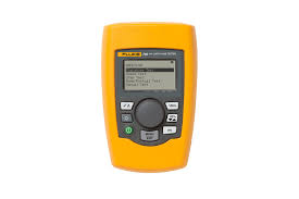
Product overview: 710 mA Loop Valve Tester
Smart Control Valve Testing is now easier than ever
The Fluke 710 Valve Testing Loop Calibrator is designed to enable users to perform quick, easy tests on HART smart control valves. Featuring built-in test procedures and an intuitive user interface, the 710 allows users to quickly and easily perform valve tests, while the valve test quick-check results provide at-a-glance diagnostics help you make maintenance decisions faster than ever. The valve health quick-check results let you know whether your valve is in good, marginal or in bad operating condition so you can quickly decide whether additional maintenance is necessary.
Valve testing and HART communication in a precision loop calibrator
With the 710 Valve Testing Loop Calibrator’s built in HART communication function, users can source a 4-20 mA signal to cause the smart control valve to move, while simultaneously interpreting the valve’s HART feedback signal to determine whether the valve is moving to the expected position. In addition to positional information, the measured pressure delivered from the valve’s internal I/P (which moves the valve) can be determined through the HART communication protocol.
The 710 has built-in test procedures that automatically increase and change the mA signal while monitoring the HART position and pressure feedback from the control valve, giving you a better overall picture of valve health at the simple push of a button.
Pre-configured valve tests, at-a-glance answers
Valve test routines built into the 710 include:
- Manual testing; manually change the mA signal and view the HART position and pressure variable information
- Full range ramping of the mA signal from 4 to 20 to 4 mA while recording the 0-100-0% position, or the pressures applied that move the valve from 0-100-0%
- Stepping the mA signal on the input to the valve in steps and evaluating the valves response to the mA input changes
- Speed tests to determine how fast the valve can open or close
- Bump and partial stroke tests that help test valves over a portion of their range so they can be tested in a live process
ValveTrack™ Software enables further analysis and trending
Valve tests that are logged and recorded to memory in the 710 are available to upload to included ValveTrack™ analysis software.
ValveTrack™ software enables you to:
- Upload, print and plot logged valve tests taken in the field
- Compare previous uploaded tests to recent tests
- View valve test history by HART Tag ID
- Export valve test data to CSV for additional analysis in Microsoft Excel®
Saving time, getting answers
In addition, the 710 offers:
- Logging of HART data in the field. Once recorded by the 710 in the field, the ValveTrack™ software can upload the HART configuration of up to (20) HART devices in your plant and output data in either (.csv) or (.txt) format.
- Data logged mA loop measurements and HART data can be recorded from a particular transmitter for troubleshooting and loop tuning. The data log feature offers selectable capture with recording intervals of 1 to 60 seconds and a logging capacity of 4910 records or 99 individual sessions. Each record contains the mA measurement and all four process variables.
Product Highlights
- Valve test procedures that deliver Good, Marginal or Bad assessment of a control valve
- Generic HART communication
- Best-in-class mA accuracy at 0.01 % measurement or source value
- Compact rugged design
- Intuitive user interface with Quick-Set knob for fast setup, easy to use
- 24 V DC loop power with mA measure mode (-25 % to 125 %)
- Resolution of 1 μA on mA ranges and 1 mV on voltages ranges
- Built in selectable 250 Ω resistor for HART communications
- Simple two wire connection for all measurements
- Auto shutdown to conserve battery life
- Variable step and ramp time in seconds
HART communication
The Fluke 710 offers a built-in HART modem to communicate the following HART commands:
- Read sensor PV information
- Read PV output information
- Read and write PV unit type, tag ID name, descriptor, and message
- Read and write PV ranges (upper and lower)
- Enter/exit fixed current mode
- Set zero offset
- Trim DAC zero (mA output 4 mA)
- Trim DAC gain (mA output 20 mA)
HART Commands for Valves
The 710 includes these unique HART commands to support control valves:
- Autotrim of valve controller
In addition, the Fluke 710 offers:
- Logging of HART data in the field. Once recorded by the 710 in the field, the ValveTrack™ software can upload the HART configuration of up to 20 HART devices in your plant and output data in either .csv or .txt format
- Data-logged mA loop measurements and HART data can be recorded from a particular transmitter for troubleshooting and loop tuning. The data log feature offers selectable capture with recording intervals of 1 to 6 seconds and a logging capacity of 4910 records or 99 individual sessions. Each record contains the mA measurement and all four process variables.
Specifications: 710 mA Loop Valve Tester
| Detailed Specifications | |
| Functions | mA source, mA simulate, mA read, mA read/loop power, and volts read. |
| Ranges | mA (0 to 24 mA) and Volts (0 to 30 V DC) |
| Resolution | 1 µA on mA ranges and 1 mV on voltage range |
| Accuracy | 0.01% ± 2 counts, all ranges (@ 23 °C ± 5 °C [73.4 °F ± 41 °F]) |
| Operating temperature range | -10°C to 55°C (14°F to 131°F) |
| Humidity range | 10 to 95% non-condensing |
| Stability | 20 ppm of F.S. /°C from -10°C to 18°C and 28°C to 55°C |
| Display | 128 x 64 pixels, LCD Graphic w/backlight, .34 high digits |
| Power | 6 AAA alkaline |
| Battery life | 40 hours continuous use (measure mode using) |
| Loop compliance voltage | 24 V DC @ 20mA |
| Over-voltage protection | 240 V AC |
| Overload current protection | 28 mA DC |
| EMC | EN61326 Annex A (Portable Instruments) |
| Dimensions (L x W x D) | 15 x 9 x 3 cm (6 x 3.6 x 1.3 in) |
| Weight | 0.3 kg (9.5 oz) |
| Included accessories | Traceable calibration certificate with data, batteries, test leads, USB upload cable and safety |
- 质量承诺
- 正品保修
- 送货到家
- 交易简单化