A DC resistance tester measures resistance by applying a controlled direct current to the item under test and observing the voltage that develops across it. This approach is particularly relevant when evaluating winding resistance, including work involving a no-load voltage regulating transformer. Understanding the measurement path and the operating precautions helps users interpret the instrument’s indications and avoid interrupting a test incorrectly.
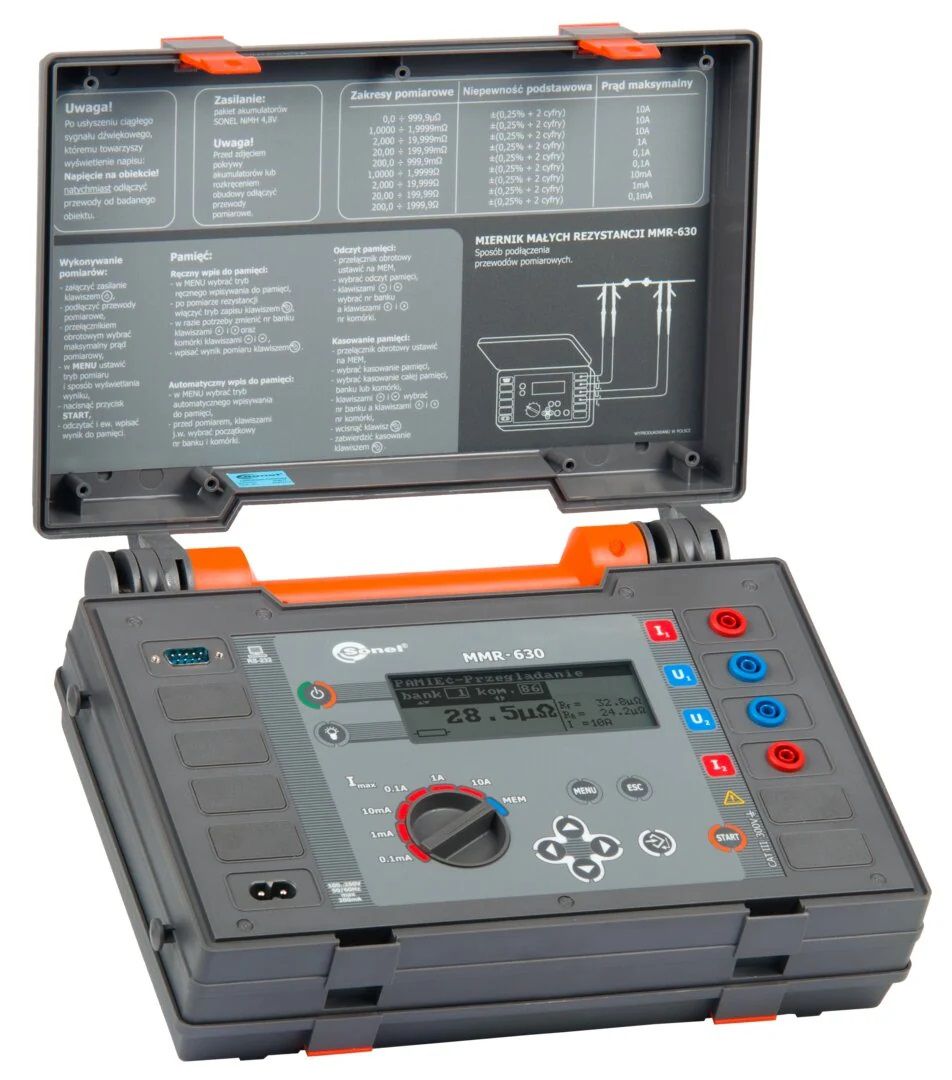
DC resistance tester working principle
The core of a winding resistance tester is a constant-current source. During a resistance measurement, this source delivers DC current to the tested product through the I+ and I- terminals. Because the current is controlled, the instrument can use the voltage response of the tested product to determine its resistance.
As the applied current passes through the resistance being tested, a corresponding voltage is generated. The tester retrieves this voltage through the separate V+ and V- terminals. In simple terms, the current terminals supply the test current, while the voltage terminals sense the voltage produced by that current.
This separation of current and voltage connections is central to the measurement arrangement described for a DC resistance tester. The instrument uses the applied current and the sensed voltage as the basis for the displayed resistance result. For dependable operation, the wiring must remain intact throughout the measurement.
Understanding the terminal roles
I+ and I- terminals: applying test current
The I+ and I- terminals form the current path. They connect the constant-current source to the tested product, allowing the selected DC current to flow through the resistance under evaluation. The magnitude of that current is related to the measurement range selected on the tester.
V+ and V- terminals: sensing voltage
The V+ and V- terminals retrieve the voltage value generated on the tested product. These terminals are used for voltage sensing rather than for feeding the test current. Keeping the current and voltage paths clearly connected as intended supports the tester’s measurement process.
Key precautions during winding resistance measurement
Testing procedures should account for the state of the circuit and the instrument indication. The following points are especially important when performing a DC resistance tester
Complete discharge before changing a tap
When measuring a no-load voltage regulating transformer, discharge must be completed before the tap switch is changed. The tap switch should only be operated after the discharge indication has ended. This sequence prevents a tap change while the tester still indicates that discharge is in progress.
Do not disconnect wiring during a test
Wiring must not be disconnected during measurement. Since the tester applies current through I+ and I- and retrieves voltage through V+ and V-, interrupting a connection breaks the intended measurement arrangement. Connections should therefore remain in place until the measurement process has been exited and the relevant indication allows the next step.
Responding to a stalled charging indication
A charging progress bar and current display that remain unchanged for a long time can indicate that the measured winding resistance exceeds the current measurement range. In this condition, the current may not reach the preset value.
The stated response is to press the Exit key to return, select a current, and try the measurement again. This gives the operator a way to adjust the current selection rather than waiting indefinitely for a value that may not be reached under the existing range.
A practical measurement sequence
- Connect the test current leads to the I+ and I- terminals and the voltage sensing leads to the V+ and V- terminals.
- Apply the selected DC current and allow the tester to obtain the voltage value from the tested product.
- Keep all wiring connected while measurement is underway.
- If the charging progress and current reading remain stagnant, exit the operation, select a different current, and repeat the test.
- For a no-load voltage regulating transformer, wait for the discharge indication to end before switching the tap.
Why procedure matters
By treating current application, voltage sensing, discharge, and range selection as connected steps, users can follow a clearer and more consistent DC resistance measurement process. For transformer winding resistance work, observing the discharge indication before changing a tap is also an essential part of the operating sequence.
The low resistance tester working principle depends on a controlled current path and a valid voltage reading. A correct terminal arrangement, uninterrupted wiring, and appropriate current selection help the instrument complete this process.