How an Oscilloscope Probe Works
In electronics testing, the oscilloscope is one of the most widely used instruments, and the probe is the part that connects the measured circuit to the scope. Although the probe may look simple from the outside, its internal design has a major effect on measurement accuracy. Understanding how an oscilloscope probe works helps explain why some waveforms appear clean while others become distorted.
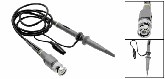
An oscilloscope probe is designed to transfer the signal from the circuit to the oscilloscope with as little interference as possible. The probe typically uses a BNC connector with shielded cable to interface with the oscilloscope. This structure helps reduce signal distortion. If ordinary two-wire connection were used instead, the waveform could be affected severely, especially when measuring fast signals.
Why Probe Design Affects the Signal
Oscilloscopes generally use a high input impedance so they do not load the circuit too heavily. Behind the probe’s BNC connector, there is often a 1 MΩ resistor or a similar input circuit. This high-impedance design helps reduce the impact on the circuit under test, but it also introduces a small capacitance at the input interface.
That capacitance can act like a filter and cause measurable waveform distortion. In practice, this means the shape of the signal shown on the screen may not exactly match the original signal unless the probe is properly designed and adjusted.
Probe Compensation and Waveform Accuracy
Many probes include a parallel adjustable capacitor. This compensation capacitor is used to offset the effect of cable capacitance and improve the displayed waveform. When the probe is connected to a square wave source, the capacitor can be adjusted until the square wave on the oscilloscope screen looks as accurate as possible.
This adjustment matters because the capacitor can influence filtering behavior. A larger capacitor can make the probe behave like a low-pass filter, while the opposite effect can occur in other conditions. For that reason, the probe should be adjusted carefully to achieve the best result during measurement.
Attenuation and Voltage Reading
Most probes also include a switchable attenuator. This feature is used to reduce the signal level so higher voltages can be read safely and more conveniently. For example, when a 10x attenuator is selected, a 1 V signal may be displayed by the oscilloscope as 100 mV.
To keep the reading correct, the oscilloscope input setting must match the probe’s attenuation setting. If the scope and probe are not set consistently, the displayed voltage value will be incorrect.
When a Standard Probe Is Not the Right Choice
Although the probe is designed to minimize disturbance to the measured circuit, it is not always suitable for every application. A low-impedance circuit, such as a 50-ohm RF output, may require a different connection method. In that case, an ordinary oscilloscope probe is usually not the best choice.
The text describes using a three-way BNC to match the 50-ohm end resistance and connect directly to the 50-ohm output. This helps ensure the measurement setup matches the circuit conditions more appropriately.
Key Takeaways
An oscilloscope probe is more than a simple wire. It is a carefully designed interface that helps transfer signals to the oscilloscope while reducing loading, controlling capacitance, and supporting accurate readings. Its BNC connector, shielded cable, high-impedance design, compensation capacitor, and attenuation switch all work together to improve measurement quality.
For electronics testing, proper probe setup is essential. Matching the attenuation setting, adjusting compensation, and choosing the right connection method for the circuit all help ensure the oscilloscope shows a more reliable waveform.