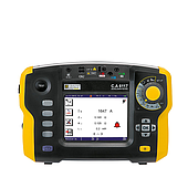
In practice, ground resistance tester is used methods such as three-point or four-point testing, depending on the grounding system and site conditions. Measurement results are affected by the electrode, the surrounding soil, and the test circuit configuration. For systems with multiple parallel grounding paths, correctly identifying the part of the system being measured is just as important as reading the value displayed on the instrument.
Auxiliary Electrode Position Can Affect the Result
When ground resistance is measured using auxiliary electrodes, the soil surrounding the electrode creates an area of electrical influence. The current and potential electrodes must be placed far enough apart to prevent these areas of influence from significantly overlapping.
If the potential electrode is located within the influence area of the electrode under test, moving it by only a few meters can cause a noticeable change in the measured value. In this case, the displayed value cannot yet be considered representative of the electrode's actual ground resistance.
One practical verification method is to move the potential electrode in both directions and repeat the measurement. If the measured values remain close to each other, the electrode position is likely within a more stable measurement region. If the readings vary significantly, the distance to the current electrode should be increased and the measurement repeated. AEMC technical documentation also uses changes in measurement results according to potential-electrode position to determine whether the measurement region is sufficiently stable.
Therefore, electrode spacing should not be selected solely according to a fixed distance. Electrode depth, the size of the grounding system, and soil characteristics can all affect the required spacing.
A Single Measurement May Include Multiple Grounding Paths
An electrode may be connected in parallel with other electrodes through protective conductors, metal structures, lightning protection systems, or other grounding connections. If a conventional measurement is performed without isolating the electrode under test from the grounding network, the instrument may detect the influence of parallel current paths.
The resulting value may therefore not represent the resistance of the individual electrode being tested, but rather the characteristics of the entire grounding network. Megger also notes that parallel paths within a grounding system can affect measurements of individual electrodes.
This creates an important distinction between two testing objectives: evaluating the entire grounding system and determining the resistance of a specific electrode. These two objectives should not be interpreted in the same way.
Fall-of-Potential and Clamp Methods Work Differently
The auxiliary-electrode method is suitable when the soil is accessible and there is sufficient space to install auxiliary electrodes. Depending on the selected test configuration, this method can be used to evaluate the resistance of an individual electrode or grounding system.
For systems with multiple parallel grounding branches, a tester supporting selective measurement can combine auxiliary electrodes with a current clamp to determine the resistance of individual branches without disconnecting the electrode from the grounding system.
Clamp-based testing without auxiliary electrodes operates under different conditions. It relies on a grounding loop with multiple parallel paths to generate and measure the test current. Therefore, if the object has only a single path to ground, this method is not suitable for determining ground resistance in the conventional manner.
This is an important consideration when selecting a tester: the number of grounding paths and whether the electrode can be isolated from the grounding network often determine the appropriate measurement method.
Stray Currents Can Enter the Measurement Circuit
An energized grounding system may carry currents from electrical equipment, leakage currents, interference, and harmonic components. These signals can enter the measurement circuit and cause the readings to fluctuate.
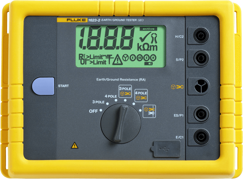
The problem is more apparent in industrial facilities, substations, and sites containing large power equipment. In such environments, selecting an appropriate test frequency can help reduce the influence of external interference. Some advanced earth resistance tester can automatically select a test frequency to identify a lower-noise measurement range.
Test cables should also be routed appropriately. A measurement cable running parallel to power cables, metal structures, rails, or other conductors can experience electromagnetic coupling that affects the measurement result.
Therefore, fluctuating readings do not necessarily indicate a problem with the grounding system itself. It is necessary to distinguish changes in the test object from interference caused by the measurement environment.
Soil Conditions Change with the Seasons
Soil resistivity depends on moisture content, soil composition, and temperature. After prolonged periods of rainfall or drought, the same grounding system may produce different resistance values.
This means that comparing two measurements taken at arbitrary times can lead to an incorrect assessment of the trend. During periodic inspections, soil and weather conditions should be recorded together with the measurement results. Megger also notes that soil resistivity can vary seasonally and should be considered when evaluating a grounding system.
A higher value than the previous measurement is not sufficient on its own to conclude that an electrode has deteriorated. The result becomes more meaningful when compared with measurements performed under similar conditions.
Do Not Evaluate a Measurement Based on a Single Value
A reliable measurement should also demonstrate repeatability. With the auxiliary-electrode method, the test can be verified by changing the position of the potential electrode or altering the arrangement of the auxiliary electrodes. If the results remain stable, confidence in the measurement increases. AEMC recommends performing measurements at different positions to identify the influence of current flow through the soil or local geological conditions.
This approach provides more useful information than simply comparing the result with a predetermined resistance threshold. Two measurements may both produce low resistance values, but a stable measurement and one that changes significantly with electrode position do not have the same level of reliability.
Test data should be recorded together with the electrode location, measurement method, electrode spacing, weather conditions, and any unusual observations at the site. Maintaining this information over multiple inspection cycles makes changes in the grounding system easier to identify.
Select a Ground Resistance Tester According to the Grounding System
Selecting a ground resistance tester should be based on the structure of the grounding system and the intended measurement method, rather than on the measurement range alone. For an independent electrode in an area with sufficient space, the auxiliary-electrode method can be used to determine its ground resistance. When a system contains multiple electrodes connected in parallel, selective measurement or clamp-based testing can be used to evaluate individual branches without necessarily disconnecting them.
Access to the test location also affects instrument selection. Confined areas, concrete surfaces, or energized grounding systems may limit the use of auxiliary electrodes, while electrically noisy environments require a tester with suitable interference-rejection capabilities.
Therefore, before selecting a ground resistance meter, determine whether the objective is to measure an individual electrode or the entire grounding system, identify the configuration of the grounding branches, assess the conditions for installing auxiliary electrodes, and evaluate the level of electrical interference at the test location.
A measurement is meaningful only when the correct object is tested using the appropriate method and the results remain stable under actual test conditions.