In partial discharge testing equipment, distinguishing signals originating from the test object from noise is essential for evaluating measurement results. Noise can enter the system through the same path as partial discharge signals via the current sensor, but it may also affect the monitoring system directly due to improper grounding, shielding, or circuit configuration.
In field environments, noise can occur in various forms and intensities depending on the measurement location. Therefore, before drawing conclusions about the condition of the test object, it is necessary to consider the noise source, coupling path, and characteristics of the received signal.
Why interference matters in partial discharge measurements
Continuous disturbances with a broadly stable amplitude are commonly treated as background noise. This noise raises the minimum discharge level that can be visibly detected by the test setup. In practical terms, the effective sensitivity of the measurement is lower than the theoretical sensitivity of the circuit.
As test voltage increases, some interference may also increase. This creates a risk that a response generated in the test circuit or surrounding environment could be interpreted as discharge within the specimen. For this reason, results should be reviewed in the context of the test circuit, the external environment, and the behavior of the signal as voltage changes.
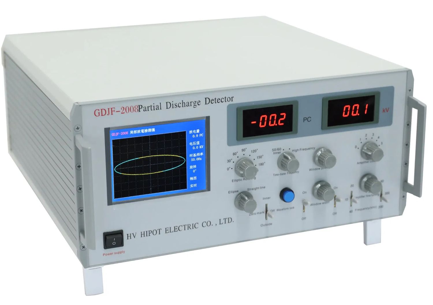
Reducing interference as far as practical supports clearer interpretation. A detector that displays the actual discharge waveform can also help distinguish spurious responses from signals associated with the test object. It does not remove the need for careful setup, but it provides more information for evaluating what the instrument is detecting.
Common types of partial discharge test interference
Interference encountered during field or laboratory testing can be grouped by its signal pattern. The following categories help organize the investigation.
Continuous periodic interference
Periodic interference repeats at regular intervals. Possible examples include higher-order harmonics, carrier-wave communication, and radio communication. Because these signals can be persistent, they may form a recognizable repeating pattern in the measurement. Their impact depends on their strength and on how they couple into the measurement point.
Pulse interference
Pulse interference may be periodic or random. Periodic pulse activity can be associated with high-frequency inrush events caused by power electronic device operation. Random pulse interference may arise from corona discharge on a high-voltage line, partial discharge from other electrical equipment, tap-switch operation, motor arc discharge, or discharge caused by poor contacts and floating potentials.
White noise and coupled noise
White noise can include thermal noise from coils, noise associated with the grounding network, power supply line noise, and noise coupled through transformer relay protection signal lines. Although such noise may not appear as a single distinct pulse source, it can still increase the background level and make low-level discharge signals harder to observe.
How interference enters the test setup
If continuous noise has a relatively uniform amplitude, the effective detection sensitivity of partial discharge detector will decrease. As a result, the smallest partial discharge signal that can be detected becomes higher than the theoretical minimum detection level of the test circuit. According to the source data, this type of noise may increase with voltage, causing a corresponding reduction in sensitivity.
Another risk is that discharge signals generated within the test circuit itself may increase as the applied voltage rises and be mistaken for partial discharge occurring inside the test object. Therefore, the appearance of a signal or an increase in signal amplitude with voltage alone is not sufficient to identify the test object as the source.
Interference sources within and around the test circuit
A useful first step is to separate sources that are present without applying high voltage from those that appear only when high voltage is applied to the circuit. This distinction can narrow the investigation and prevent premature conclusions about the specimen.
- Power supply interference: Noise can affect the measurement when the control section, voltage regulator, and transformer are connected, even before voltage is raised.
- Grounding system interference: Poor grounding or multiple grounding paths can create potential differences between instrument connection points and cause measurement deflection.
- External electromagnetic interference: Radiation or electromagnetic coupling from nearby sources can enter the circuit.
- Test circuit discharge: Unwanted discharge within the test circuit can resemble activity from the specimen.
- Contact noise: Poor contacts in test leads or in the sample can create noise and unstable responses.
Key Considerations When Evaluating Signals
The practical objective is to reduce noise to the lowest possible level and identify the source of each signal with caution. Observing the actual discharge waveform can help distinguish noise responses from signals believed to originate from the test object. Grounding, shielding, connection cables, and components within the test circuit should also be checked for proper configuration.
A proper understanding of partial discharge analyzer provides a more reliable basis for measurement and evaluation. It helps prevent important signals from being missed due to an elevated noise floor while reducing the risk of interpreting noise pulses as defects in the test object.