OLTS vs. OTDR is not an either-or choice in a complete fiber testing process. An OLTS measures the end-to-end insertion loss of a fiber link, while an OTDR identifies and locates events such as connectors, splices, bends, and reflections along that link.
For final application compliance, OLTS testing provides the definitive total-loss measurement. OTDR characterization adds diagnostic detail that can reveal localized loss or reflectance issues that an overall loss result does not show.
Summary: OLTS measures total insertion loss from one end of the link to the other. OTDR analyzes reflected and backscattered light to locate individual events. Tier 1 refers to OLTS testing; Tier 2 or extended testing combines OLTS and OTDR results. Clean, inspected fiber end faces are essential before testing.
What is the difference between an OLTS and an OTDR?
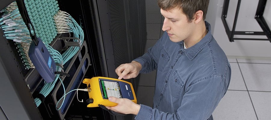
An Optical Loss Tester (OLTS) directly measures how much optical power is lost across the complete link. It uses a light source at one end and a power meter at the far end, then compares the transmitted and received light.
An Optical Time Domain Reflectometer (OTDR) sends pulses into the fiber and measures light that returns to the instrument. It uses reflected and backscattered light to characterize events and estimate loss at locations along the fiber.
| Test method | Primary measurement | What it helps identify |
|---|---|---|
| OLTS | Total end-to-end insertion loss | Whether overall link loss is within the applicable limit |
| OTDR | Reflected and backscattered light by distance | Locations and behavior of connectors, splices, bends, breaks, and link ends |
Why is OLTS used for final fiber insertion-loss testing?
OLTS is used because it provides the most accurate and repeatable measurement of a link’s total insertion loss. The measured value can be compared with the loss limit and maximum length applicable to the intended fiber application.
TIA and ISO use the term Tier 1 for testing with an OLTS. A basic light source and power meter can also measure loss, but an OLTS may add practical functions such as duplex testing, bidirectional testing, preloaded limits, length measurement, and pass/fail reporting.
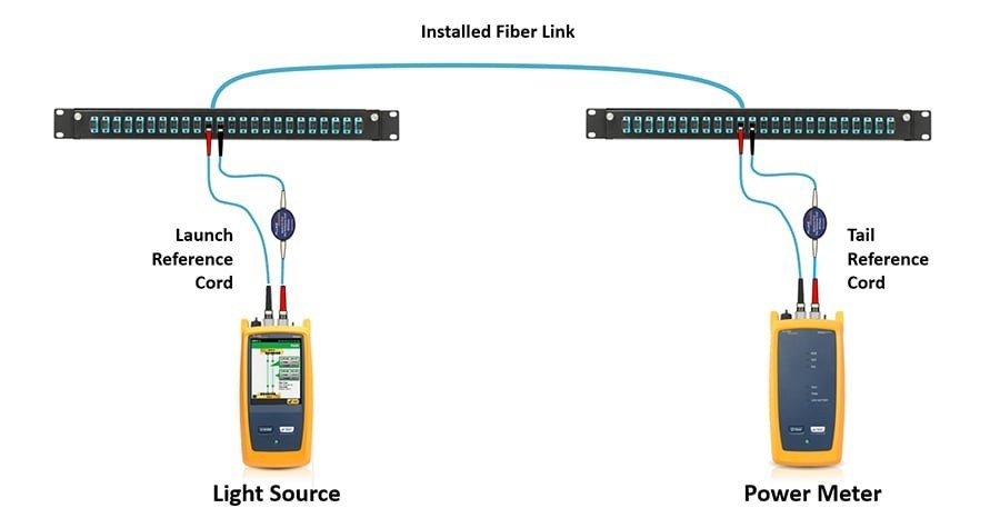
What can an OTDR find that an OLTS cannot show?
An OTDR can show where individual events occur within a fiber link. This is useful for locating questionable connectors, splices, breaks, sharp bends, and other changes that affect reflected or transmitted light.
An OLTS may report an acceptable total loss even when one event has elevated loss and another event has lower loss. OTDR characterization makes individual event locations visible, helping technicians investigate potential installation or cable-management issues before the link is placed in service.
OTDR testing can also establish the number of connections in a link. That detail is valuable when a link may contain unplanned cross-connects or patched sections that add connection points and consume the application’s loss budget.
Why does reflectance matter in short-reach single-mode fiber links?
Reflectance is the amount of light reflected back toward the source, expressed as a negative dB value for passive optics. A value closer to zero represents greater reflectance, which is associated with poorer connections and greater loss.
Reflectance is particularly relevant to emerging short-reach single-mode applications, including 100GBASE-DR, 200GBASE-DR4, and 400GBASE-DR4. Their insertion-loss limits can depend on both the number of connections and their reflectance performance.
| Term | How it is expressed | Practical meaning |
|---|---|---|
| Reflectance | Negative dB value | Measures reflected light relative to the source pulse; farther from zero is better |
| Return loss | Positive dB value | Describes signal loss related to reflected power; farther from zero is better |
Note: Multimode transceivers are more tolerant of reflection than single-mode transceivers. For high-power single-mode lasers, excessive reflection can damage the transceiver.
How should an OTDR trace be read at a basic level?
An OTDR trace plots optical power against distance: the vertical axis represents power level, and the horizontal axis represents distance along the fiber. The trace generally slopes downward as attenuation accumulates over distance.
Sharp changes in the trace can indicate connectors, splices, or breaks. A large reflection commonly marks the end of the fiber, while small apparent events after the fiber end can be ghost events rather than actual link faults.
Testing in both directions is important because a connection can display different backscatter behavior depending on direction. Bidirectional results are averaged to obtain a more accurate loss value for specific connectors and splices.
When should OLTS and OTDR be used together?
Use both methods when the project specification calls for OTDR characterization, described as Tier 2 in TIA terminology and extended testing in ISO terminology. The OLTS result verifies overall insertion loss, while the OTDR provides event-by-event characterization.
Even when OTDR testing is not explicitly specified, it can be useful before final OLTS testing. Finding the number, location, and performance of events during installation gives the team an opportunity to correct issues before documenting the final end-to-end result.
OTDR does not replace OLTS for final total-loss verification. OTDR insertion loss is inferred from returned light, whereas OLTS directly measures the light received at the far end of the link.
Why should fiber end faces be cleaned and inspected before testing?
Contaminated connections are a major cause of fiber-related problems and test failures. A particle on the fiber core can introduce loss and reflections, which can distort results or reduce link performance.
Inspect both ends of test reference cords, fiber jumpers, pre-terminated trunk cables, connectors, and relevant test adapters before mating. If cleaning is required, the end face should be cleaned with a purpose-designed fiber-optic cleaning method and left free of solvent residue.

What documentation should be retained after fiber testing?
Retain the final OLTS insertion-loss result together with OTDR traces when both tests are performed. The total-loss measurement records link compliance at installation, while the trace provides a baseline for later troubleshooting.
If performance changes after the cabling plant is live, a new OTDR trace can be compared with the original record to help determine whether a new event appeared or whether an existing connection changed over time.