Many Electrical Systems Are Not Overloaded, Yet RCCBs Still Trip Randomly
Leakage current today is very different from the traditional type of electrical leakage seen in the past. Previously, leakage current was mainly caused by moisture, damaged insulation, or conductors making contact with grounded metal surfaces. In those situations, a normal clamp meter was usually sufficient to detect abnormalities.
Today, however, systems equipped with variable frequency drives (VFDs), UPS units, switching power supplies, or solar power systems can generate leakage currents containing high-frequency pulses and harmonic components that many conventional measuring instruments can barely detect. As a result, RCCBs or ELCBs are increasingly tripping unexpectedly even though the electrical system appears to be operating normally. In many cases, the problem persists despite using a leakage current clamp meter, performing insulation resistance tests, and even replacing the residual current breaker itself.
RCCBs Do Not React Only to Ground Faults
A common misconception is that an RCCB trips only when there is leakage current flowing to ground.
In reality, an RCCB operates by comparing the outgoing and returning current. Even a brief imbalance large enough within a very short period can trigger the device, despite there being no obvious short circuit or insulation failure.
In environments using VFDs or large electronic power loads, the current waveform is no longer a pure sine wave. PWM pulses generated by inverters continuously create high-frequency components. These pulses can produce instantaneous leakage currents through parasitic capacitance between conductors, motors, and grounding systems. This phenomenon is known as capacitive leakage — a type of leakage caused by the inherent capacitance of cables and equipment rather than insulation failure.
The longer the cable runs, the larger the motors, or the faster the inverter switching speed, the greater this type of leakage current becomes. In many cases, the total load current remains completely normal, yet the RCCB still trips when the motor accelerates or when the inverter changes PWM operating states.
Harmonic Leakage: The Type of Leakage Many Clamp Meters Cannot Measure Accurately
Harmonics generated by VFDs and nonlinear loads can cause leakage currents to appear across multiple frequency ranges instead of only at 50 Hz. Under these conditions, conventional clamp meters may accurately measure only the fundamental frequency component while missing the high-frequency noise entirely. As a result, technicians may see only a few milliamps of leakage current even though the RCCB continues to trip repeatedly.
This is not necessarily a fault of the instrument itself. Most general-purpose clamp meters are optimized for residential electrical measurements or standard AC current detection. Their limited bandwidth prevents them from fully reflecting actual leakage current conditions in modern industrial environments.
Some dedicated leakage current clamp meters use highly sensitive magnetic cores and specialized filtering circuits to detect leakage current across a much wider frequency range. This difference becomes especially noticeable when testing systems involving VFDs, UPS units, or solar inverters.
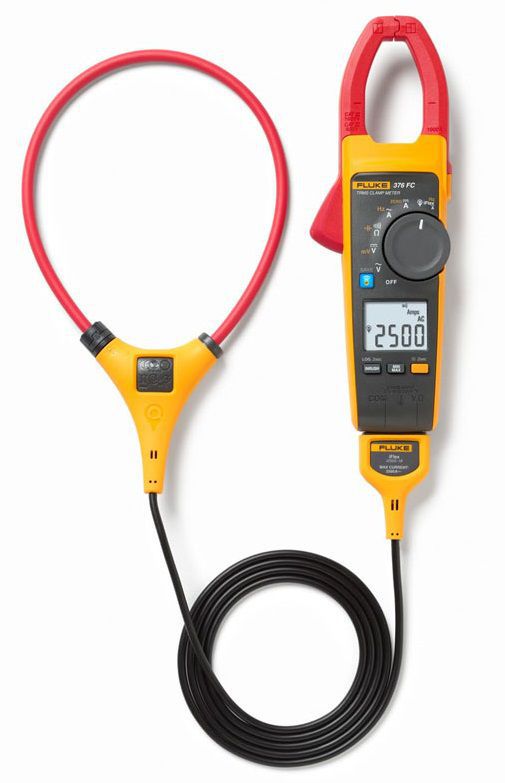
Why Leakage Current Clamp Meters Can Easily Lead to Misdiagnosis
Unlike multimeter, leakage current clamp meters are designed to detect extremely small currents, often at the milliamp or even microamp level.
Inside industrial electrical panels, the magnetic fields generated by large power conductors can directly interfere with these low-level measurements. If the clamp jaw lacks sufficient sensitivity or poor noise rejection capability, the displayed readings may fluctuate continuously. Many technicians observe only “insignificant” leakage current and conclude that the RCCB itself is defective, while the real issue is actually the accumulation of high-frequency pulse leakage from multiple devices.
This is also why many factories replace RCCBs multiple times without eliminating random tripping events.
The critical factor is not simply how many milliamps can be measured, but understanding at which frequency the leakage occurs, when it appears, and what mechanism generates it. As electrical systems increasingly rely on nonlinear loads, using the wrong measuring instrument not only wastes troubleshooting time but can also lead to unnecessary equipment replacement, prolonged downtime, and difficulty identifying the real cause of repeated RCCB tripping.
For maintenance teams needing a versatile clamp meter with strong technical capability for industrial electrical systems, the Hioki CM4001 is often considered a well-balanced option in terms of stability, noise handling, and investment cost.
Fluke 369 FC is a higher-end solution particularly suited for electrically noisy environments with significant high-frequency interference. It stands out for its ability to measure extremely small leakage currents with microamp-level resolution, along with filtering functions that suppress unwanted noise from inverters and switching loads. Its large 61 mm clamp jaw is also convenient for measuring large power cables or multiple conductors simultaneously.