A satisfactory ground resistance reading alone is not enough to confirm that the system is safe. Oxidized connections, broken grounding conductors, or lost bonding between the PV frames and the grounding system can all interrupt the intended current path.
1. Check Grounding Conductors and Connection Points
Start at the PV array and inspect the conductors connecting the module frames, aluminum rails, and metal structures to the grounding system.
Check clamps, bolts, cable lugs, and conductors for signs of looseness, oxidation, damage, or deformation. Outdoor connection points are exposed to water, humidity, and temperature changes, making them susceptible to deterioration over long periods of operation.
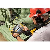
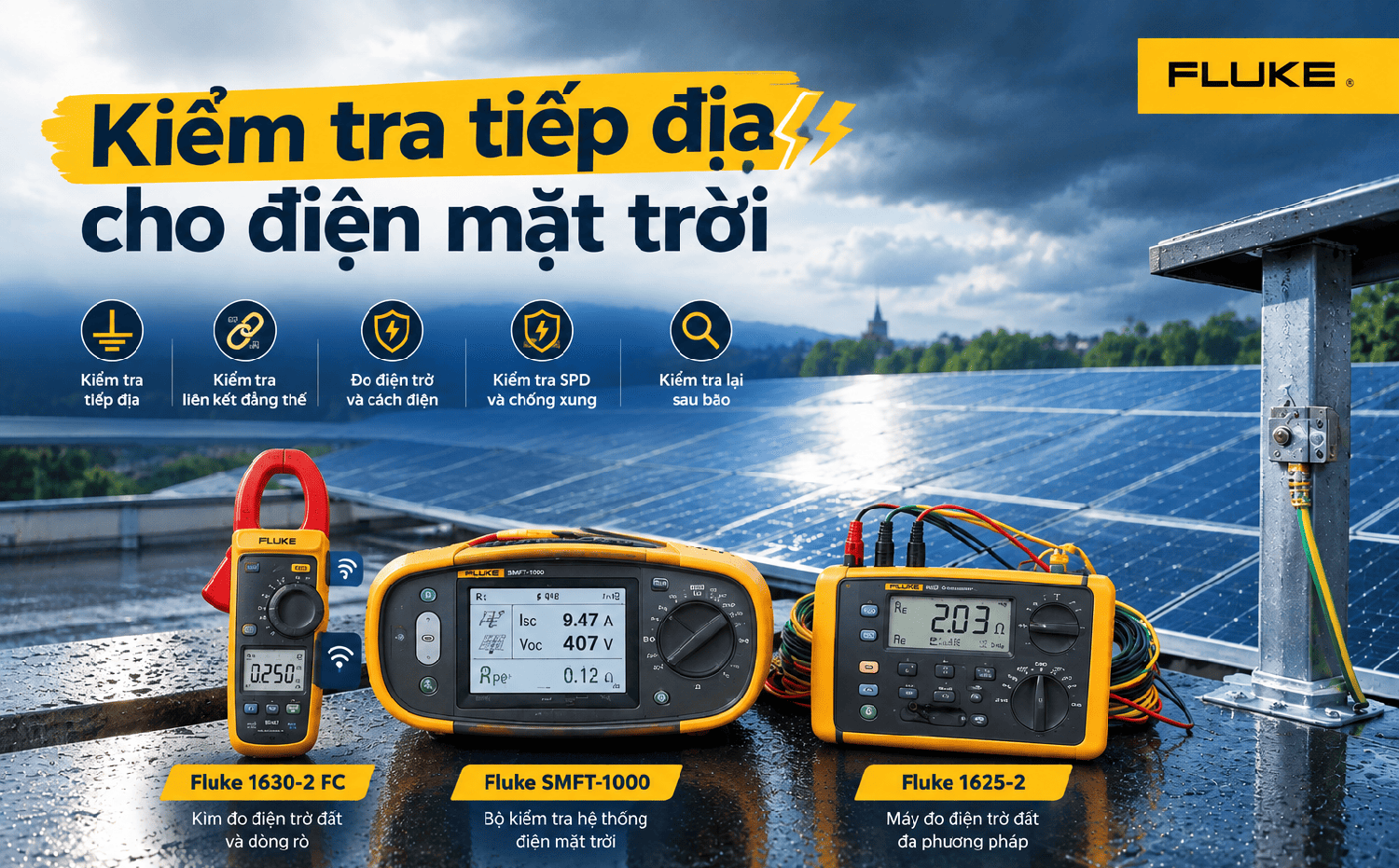
For periodic inspections, the Fluke 1625-2 Ground Resistance Tester can be used to evaluate ground resistance using methods suitable for the system configuration. The instrument supports 3- and 4-pole measurements, selective measurements with or without current clamps, and stakeless ground loop measurements for systems with multiple grounding points.
2. Check Equipotential Bonding of the PV Array
Module frames, rails, cable trays, and other metal structures on the roof should be bonded according to the system design to provide a continuous electrical path.
If a bonding connection is lost after maintenance, module replacement, or rail removal and reinstallation, fault current and transient current may not follow the intended path.
At locations where access is difficult or driving test rods is impractical, the Fluke 1630-2 can be used to measure ground loop resistance and leakage current without disconnecting the grounding electrode in suitable configurations.
The inspection should not focus only on whether the grounding conductor is intact. The entire path from the PV frame to the grounding system should be checked for electrical continuity.
3. Measure Ground Resistance
Visual inspection can only identify external defects. To evaluate the system's ability to conduct current into the ground, ground resistance should be measured using a method appropriate for the installation design.
A single ground resistance value should not be applied to every system. The required value depends on the grounding design, lightning protection system, and applicable standards.
The Fluke 1630-2 Ground Resistance Clamp Meter supports multiple measurement methods, including ground resistance measurement with test stakes and stakeless ground loop measurements. It also provides interference voltage detection and measurement frequency selection to help reduce the effects of electrical noise during testing.
In addition to recording the current measurement, inspection results should be documented after each maintenance cycle. An unusual change compared with previous measurements may indicate a need to inspect the grounding electrodes, conductors, or connection points.
4. Check Insulation and Surge Protection
Grounding does not operate independently from the DC and AC electrical systems or surge protective devices (SPDs). A PV system also requires insulation testing to identify potential leakage between the DC circuit and ground.
For solar PV systems, the Fluke SMFT-1000/KIT PV Analyzer can perform tests such as protective conductor resistance, insulation resistance, open-circuit voltage, current, and polarity. The instrument is designed for PV systems up to 1000 V DC and supports testing in accordance with IEC 62446-1.
For dedicated insulation resistance testing, the Fluke 1587 FC Insulation Multimeter combines insulation testing with multimeter functions such as voltage, resistance, current, and continuity measurements.
SPDs should also be checked for the condition of their indicators, connections, and any signs of damage after major electrical surges. Measuring ground resistance alone should not be used to conclude that the entire lightning protection system is functioning properly.
5. Recheck the System After a Storm
After a major storm, inspect the conductors, connections, electrical enclosures, and rooftop structures again. Strong winds can move cables or fittings, while rainwater can enter junction boxes and accelerate corrosion.
If the system shows abnormal signs after a storm, grounding tests can be combined with electrical testing of the PV system. The SMFT-1000 is suitable for PV system safety and commissioning tests, while the Fluke 1625-2 is designed specifically for grounding system measurements.
If the system has experienced a lightning strike, an SPD fault indication, burnt connectors, or electrical abnormalities, isolate the system and have it assessed by a qualified technician.
For rooftop solar PV systems, grounding should be inspected as a continuous path from the PV array to earth, together with equipotential bonding and surge protection.
The inspection sequence can begin with:
Visual inspection → bonding and continuity → ground resistance → insulation → SPD
The system should then be inspected again after major storms.
For more comprehensive testing, different instruments can be selected according to the measurement task: the Fluke 1625-2 for ground resistance, the Fluke 1630-2 FC for ground loop resistance and leakage current measurements where appropriate, the Fluke SMFT-1000 for PV system safety testing, and the Fluke 1587 FC for insulation testing.
Safety note: Do not work on PV modules, DC cables, or lightning protection systems during thunderstorms. Solar panels can still generate voltage when exposed to light. Electrical measurements on PV systems should be performed by qualified personnel following the appropriate isolation and safety procedures.