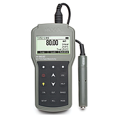
Oscilloscope screen
On the digital Oscilloscope screen, there are always divisions, helping users to easily read and analyze signals.
The size of each cell is not fixed but can be changed through the horizontal and vertical axis adjustment system. Normally, the vertical axis is calculated in volts/div, while the horizontal axis is calculated in time units (time/div).

With traditional analog oscilloscopes, the screen usually only displays monochrome. Meanwhile, modern oscilloscope models are equipped with color screens, supporting faster and more accurate distinction and identification of waveforms.
Vertical axis system of oscilloscope
The vertical axis on the oscilloscope controls the voltage scale displayed on the screen. Typically, most oscilloscopes incorporate two main knobs: Volts/div and Position.
- The Volts/div knob in the Vertical system allows you to change the voltage sensitivity, similar to zooming in or out of the waveform. Rotating clockwise will reduce the display amplitude (zoom out), while rotating counterclockwise will magnify the signal (zoom in). When the scale is small, the screen can only display low voltage signals; for detailed analysis, engineers can increase the magnification.
- The Position knob moves the waveform up or down on the display. Rotating clockwise moves the waveform down; rotating counterclockwise moves the waveform up. This is a way to “align” the entire waveform, especially useful when the signal is out of the display area.
Oscilloscope horizontal axis adjustment system
The horizontal axis on the oscilloscope is responsible for controlling the display time of the signal. Similar to the vertical axis, it is also equipped with adjustment knobs that allow you to zoom in or out of the waveform horizontally.
The horizontal axis scale is usually expressed in seconds per cell (s/div). When you turn the knob clockwise, the time period observed on the screen is expanded, allowing you to display more wave cycles at the same time. Conversely, turning it counterclockwise will “zoom in”, allowing you to observe each small part of the signal in more detail.
Refer to related articles:
The easiest guide to using an oscilloscope
What are the common functions of handheld oscilloscopes?
Why should you buy a handheld oscilloscope?
The benefits of using the KEYSIGHT EDUX1052A digital oscilloscope
Trigger system on oscilloscope
Triggers act to “fix” the waveform so that the image does not drift, so that users can observe and analyze the signal more stably.
Some common Trigger modes include:
- Edge Trigger: This is the most basic form, allowing the device to lock the signal based on the rising edge or falling edge of the wave.
- Pulse Trigger: Used to capture and lock a pulse with specific characteristics of width or amplitude. For example, a pulse from 0V → 5V → 0V can be specified for precise observation.
In modern oscilloscopes, the Trigger system is increasingly diverse, supporting engineers to analyze many types of complex signals with higher stability. If you need detailed advice on oscilloscope models suitable for the lab or field, please contact EMIN for support.