Identifying and checking phase sequence is not difficult, but requires the operator to clearly understand the principles and use the correct method. With modern equipment, this process has become much simpler and faster. This article will help you gain more basic knowledge to apply effectively in your daily work.
First of all, what is phase order?
Phase sequence (phase sequence) is the order in which the individual phase voltages in a three-phase power system reach their maximum value. It determines the direction of rotation of the three-phase motor and ensures correct operation of the electrical equipment in the system.
In a three-phase system, the three currents must have the same magnitude, frequency, and phase difference of exactly 120 degrees relative to each other. When current flows through the coils, the order of the input conductors determines the direction of the magnetic field created. If the phase sequence is wrong, the motor can rotate in the opposite direction, affecting performance or even damaging the equipment.
Why is determining phase order important?
In a three-phase power system, determining the phase order plays a very important role, because it determines the correct operation of electrical equipment. If the phase sequence is wrong, the motor may rotate in the wrong direction, affecting performance, potentially causing equipment damage or unsafe operation.
Not only that, determining the correct phase order is also a key factor when connecting three-phase electrical systems together. If the phases are not synchronized, phase conflicts can occur, causing serious problems for the entire system.
Therefore, during the design, installation and maintenance process, checking and ensuring correct phase order is a mandatory requirement, helping the electrical system operate stably and safely.
Principle of measuring phase sequence that you should know
Currently, two popular types of machines for detecting phase sequence in three-phase power systems are rotary type and static type. Each type has its own operating principle, suitable for each specific application.
Measuring principle of rotary type phase indicator meter
Rotary type phase indicator operates on the principle of induction motor. Similar to a three-phase motor, when the R, Y, B phases are supplied in the correct sequence, the meter will rotate clockwise, indicating that the phase sequence is correct.
On the contrary, if the phase sequence is reversed, the direction of rotation of the clock will be counterclockwise, while also warning the user about the risk of incorrect phase sequence. This is very important because phase sequence errors can greatly affect the operation of the motor or cause damage to other devices in the system..
Measuring principle of static type phase indicator meter
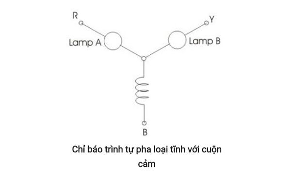
The static type uses components such as lamps, inductors or capacitors to check phase sequence. In there:
- One lamp is connected to phase R, the second lamp to phase Y, and the inductor or capacitor will connect to phase B.
- If a choke is used, when the phase order is correct, the lamp connected to phase Y will be brighter than the R headlight. Conversely, if the phase sequence is wrong, the R headlight will be brighter.
In the case of using a capacitor, the light principle of the lamp will also change: when the phase order is correct, the R lamp is brighter than the Y lamp, and when the phase order is wrong, the Y lamp will be brighter or the R lamp may turn off completely. .
How to determine standard phase order like an expert
Determining phase sequence is an important step in a three-phase power system. Currently, specialized techniques and equipment such as wave meters, electrical network analyzers, or supporting software are used to ensure accuracy. However, some simple methods can also help check the phase order quickly.
1. Visual observation method
Determining the phase order by eye is a simple but useful way in many cases, especially when specialized measuring equipment is not available. This method is based on distinguishing the colors of the phases in a three-phase power system, often denoted as R (red), Y (yellow), and B (blue).
You need to use a pair of probes that are clearly marked, for example red and blue. Place these two probes on the phases one after another and observe the color change when moving them between phases. If the phase order is correct, when moving from R to Y phase, the color will transition from red to yellow, and from Y to B will transition to blue.
If the colors do not change in the R-Y-B sequence but are reversed, you can determine that the phase order is not correct.
* Limitations of the method:
Although convenient, this method has low accuracy and is easily affected by lighting conditions, the operator's ability to observe, or the probe not being clearly marked. Therefore, it should only be considered as a preliminary test or as a supplement to specialized measuring equipment.
2. How to determine the phase order using an electric tester
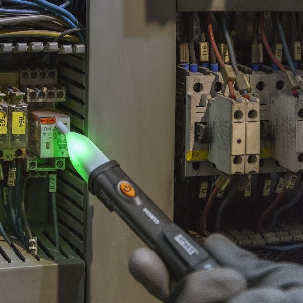
Determining the phase sequence with an electrical tester is a simple and common method in electrical applications, suitable for quick checks in not too complex systems. Here are the steps:
Step 1: Ensure safety before starting. Double check that the circuit is de-energized and free of dangerous voltages.
Step 2: Prepare the electric test pen. Connect the electrical tester to the system to be tested.
Step 3: Test each phase. Place the electric tester in turn on each phase wire in the system. Observe the response of the electric tester, if the light comes on at a certain phase, you have identified the corresponding phase wire.
Step 4: Check again. After roughly determining the phase sequence, check again to ensure that the phases are connected in the correct sequence..
Note:
This method is only basic and suitable for small systems that require little or no high precision. For complex applications or requiring absolute accuracy, specialized equipment such as phase sequence meters or alternating current meters should be used to ensure the most accurate results.
3. How to determine phase sequence using a phase sequence meter
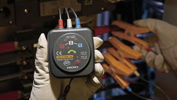
The phase sequence meter is a specialized device that helps determine the phase sequence in AC power systems, and also checks the rotation direction of the motor or distinguishes the phase sequence when installing high voltage systems. , low, or overload and phase shift protection devices. Below are the detailed steps:
Step 1: Check the operation of the meter
Before taking measurements, check the stability of the device by:
- Use a clip with an alligator clip to connect to an alternating current (AC) power source with a voltage of about 70V.
- Observe the indicator lights on the machine:
- Light on: The device is operating normally, ready to use.
- The light does not light up: The machine may be defective and need to be repaired or replaced before use.
Step 2: Check if the wire is working
Use voltage clamps to check the wires. The results will display as follows:
- R clip (red): Displays the RS indicator.
-S clip (white): Displays RS and ST indicators simultaneously.
- T clip (green): Displays the ST indicator.
This helps confirm that the phase wires are energized and ready to check the phase sequence.
Step 3: Measure the phase sequence
Connect the clamp terminals of the meter to the conductors of the 3-phase electrical system (outside the insulation layer) in sequence and proceed as follows.:
- Observe the voltage indicator: If the indicator lights of both RS and ST wires are lit, this confirms that the phases are working.
- Check the phase sequence indicator: If the light or display flashes in the order of the arrow (RST), it means the phase sequence is connected correctly. At the same time, the device will emit an intermittent notification beep.
Note:
Using a phase sequence meter helps ensure accurate connection and minimize risks when installing and operating a 3-phase electrical system.