Definition of earth resistance:
Earth resistance is a concept used to refer to the ability of soil to resist electric current, measured by the resistivity of a cube of soil measuring 1m³, with current flowing from one side to the opposite side.
Soil is a porous material with a complex structure consisting of three main components: solid, liquid and gas.
- Solid: Consists of tiny mineral particles, sizes from 0.1mm to 3mm, and organic compounds from microorganisms and plants.
- Liquid (soil solution):** This is water containing minerals and dissolved substances from solid and gas particles.
- Gaseous form: Mainly oxygen, nitrogen and carbon dioxide, filling the pores in the soil.
In soil, the main conductive part is the soil solution. Hard particles such as minerals only conduct electricity very weakly, but when there is a solution containing ions, electric current will be conducted through the movement of ions in an electric field. The higher the ionic concentration of soil, the better its ability to conduct electricity.
Currently, grounding resistance standards have been clearly specified in Vietnamese Standard TCVN 4756:1989. These regulations help construction workers measure and install electrical systems in the most effective and safe way.
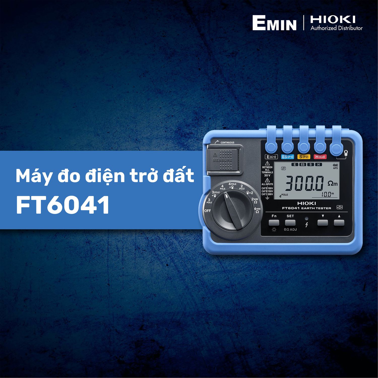
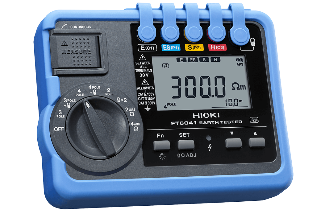
Hioki FT6041 earth resistance measuring device can meet most of the criteria:
About measuring function:
Below are the common measurement functions of the Hioki FT6041
- 4-pole measurement method
When conducting a construction design survey, measuring ground resistance is an important step.
Soil resistance varies depending on the geology of each area. In this process, earth resistance assessment helps determine the optimal location, shape, size and characteristics of ground electrodes before building construction.
- 3-pole measurement method
This is a method of accurately measuring earth resistance using auxiliary electrodes.
This method is often applied during post-construction completion inspection or periodic maintenance, ensuring highly reliable measurement values.
- MEC function
Earth resistance measurement technology does not require disconnecting the grounding system.
Incorporating a clamp sensor to measure the current into the electrode under test, MEC helps eliminate influences from surrounding areas. Significantly shortens measurement time.
- 3-pole measurement method with 4 measuring points
When the ground resistance value is very small (several ohms or less), the test lead resistance can distort the results.
The 4-point measurement method overcomes this problem, allowing for more accurate testing by eliminating the influence of test lead resistance.
- 2 clamp measurement method
Suitable for measuring at multiple points without the use of auxiliary electrodes.
This method uses a voltage injection clamp and a clamp sensor to measure the current. Then, the ground resistance is calculated without inserting additional electrodes into the ground, making the operation quicker.
- Low impedance measurement method
This is a continuous check step after measuring earth resistance using the 3-pole method.
When the electrodes are reconnected to the power system, a low resistance should be measured to ensure system continuity.
Optimal design:
- Fast measurement time, coils do not get tangled or twisted: The combination of the ability to display measurement values after only 6 seconds (3-pole method) and easy-to-use coil design helps optimize working time job.
- Only one insertion is required thanks to the maximum allowable resistance of up to 100 kΩ: This method uses an injection clamp to apply the voltage and a clamp sensor to measure the current, then calculate the ground resistance. There is no need to insert additional auxiliary electrodes into the soil, just attach two clamps to the electrode being measured.
- Take measurements even on concrete
*Newly designed Earth Nets L9846 Module :This module serves as an auxiliary electrode specifically for flat surfaces where traditional pins cannot be used. When opened, two copper grids come into direct contact with the surface. Simply pour water on to measure earth resistance without any other electrode insertion.
Sensor pliers are ideal for tight spaces
When ground electrodes are installed in space-constrained areas or bus bars have large thicknesses, the CT9848 sensor pliers are the perfect choice. With a thin and wide pincer design, clamping ground electrodes is easy, gentle and effective even in the most difficult working conditions.
Wireless support – Easily transmit measurement data
The Hioki FT6041, when combined with the Wireless Adapter Z3210 (purchased separately), allows measurement data to be transferred directly to a smartphone or tablet. Quickly create reports with images and drawings right on site.
GENNECT Cross application
GENNECT Cross is free software developed by Hioki specifically for measuring devices. This application supports checking, managing data and creating reports easily. You can take photos of the measurement location, record measurement results directly on the image, add handwritten notes and store data scientifically, helping to optimize field workflow.
![[EMINxKeysight] International Electronics & Smart Manufacturing Exhibition 2026](/s-cdn/6b/6b7bfde66a6bed35f68df9f0109b0179163d72d8.png)