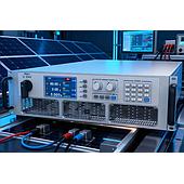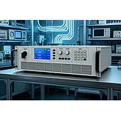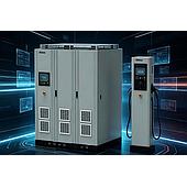
A programmable DC electronic load is used in EV charger testing to apply controlled electrical demand to a charging module and observe how the module responds. It supports evaluation of efficiency, output-voltage stability, protection behavior, thermal behavior, and load sharing in high-voltage fast-charging applications.
For charging systems moving toward 400 V and 800 V platforms, the test load must cover the intended voltage and current conditions while reproducing rapid changes in demand. The available test data describes applications ranging from 150 V to 1,000 V and power transitions used to assess module response.
Summary: Programmable DC loads can map efficiency across an operating range, create rapid power changes, simulate output faults, and assess current balance in parallel modules. For a 480 kW charging-station example, the cited selection criteria include 150–1,000 V coverage, a current ramp rate of at least 50 A/μs, and protective functions.

What does a programmable DC electronic load do in EV charger testing?
A programmable DC electronic load absorbs power from the charger under test at defined voltage, current, resistance, or power conditions. This makes it possible to characterize a charging module without connecting an actual vehicle battery.
The load can be adjusted over a planned operating range, then changed quickly to observe whether the module maintains stable output. In the supplied example, current is adjusted from 0 A to 500 A in 10% steps while output voltage is evaluated between 300 V and 1,000 V.
How can a DC electronic load be used to map charging-module efficiency?
Efficiency mapping is performed by testing the module at multiple output-voltage and load-current points rather than relying on one nominal operating point. The resulting map can reveal operating regions where efficiency falls and can guide further thermal investigation.
The provided scenario uses 10% current increments across a 0–500 A range at 300–1,000 V. It also describes using thermal imaging to locate hotspots above 105°C when reviewing thermal design.
| Test activity | Conditions described in the source data | Purpose of the check |
|---|---|---|
| Efficiency mapping | 0–500 A in 10% steps; 300–1,000 V output range | Identify efficiency changes across the power range |
| Thermal review | Thermal imaging for hotspots above 105°C | Support thermal-design assessment |
| Voltage ride-through | 50 kW to 200 kW to 50 kW transition | Observe dynamic output-voltage response |
Why are rapid load changes important for high-voltage fast-charging modules?
Rapid load changes help evaluate whether a charging module can remain stable when power demand shifts suddenly. This is relevant because a dynamic response problem can cause output-voltage movement that disrupts charging control.
One cited test holds 50 kW for 10 seconds, increases to 200 kW in 0.1 seconds, and then returns to 50 kW. The stated qualification target for that example is an output-voltage fluctuation of no more than ±5%.
The source data identifies a current ramp rate of at least 50 A/μs as a selection criterion for matching the switching speed of a SiC-based module. Test requirements should still be aligned with the specific module and applicable test plan.
How is protection behavior evaluated with a DC electronic load?
Protection behavior can be evaluated by applying abnormal conditions in a controlled test setup and recording the module response time. The supplied examples include high-voltage stress and a simulated output short circuit.
For insulation-related testing, the data describes simulating a 150% overvoltage condition, such as a 1,200 V withstand test, and checking whether a protection circuit responds within 2 ms. For fault injection, it describes a short-circuit simulation with resistance at or below 5 mΩ and a protection-triggering requirement of no more than 100 μs.
How can parallel charging modules be checked for current sharing?
Parallel modules should be checked for balanced current distribution because unequal sharing can place excessive stress on one module. Multiple loads can be synchronized through CAN bus communication to reproduce a larger power step.
The described example simulates a 500 kW power step and uses a current-imbalance target of no more than ±2% between modules. This test focuses on whether modules respond together rather than allowing one unit to carry a disproportionate share of the load.
What DC electronic load capabilities are relevant for a 480 kW charging-station example?
For the cited 480 kW example, the load should cover the voltage span needed by 400 V and 800 V charging platforms, respond quickly to transient demand, and include protection against incorrect or excessive test conditions.
| Capability | Value or function cited for the example | Testing relevance |
|---|---|---|
| Voltage coverage | 150–1,000 V | Supports the stated 400 V and 800 V platform range |
| Transient response | Current ramp rate ≥50 A/μs | Applies rapid demand changes during dynamic tests |
| Overvoltage protection | Hardware OVP threshold ≥1,100 V | Helps protect the test setup during excessive-voltage conditions |
| Reverse-polarity protection | Protection function specified | Helps reduce damage risk from incorrect connection |
What future test conditions may require wider DC load capability?
Higher-voltage DC charging concepts may require test loads with a wider operating range. The source data gives a 1,500 V photovoltaic DC charging-station example that calls for 0–1,500 V capability with ±1% accuracy.
More realistic testing may also use vehicle-like charging curves instead of only fixed load points. The supplied example mentions a peak current of 615 A for a Tesla V4 Supercharger charging curve; this is presented as an example of the type of demand profile a test setup may seek to reproduce.
When should a test team choose a programmable DC electronic load?
A test team should choose a programmable DC electronic load when it needs repeatable control of steady-state demand, fast power transitions, or fault conditions during EV charging-module evaluation. The relevant voltage range, current capability, response speed, synchronization needs, and protection functions should be defined from the charger’s intended test conditions.
The supplied material cites the AN23624E series as an example associated with high-precision dynamic response and synchronous control. Whether a particular load is suitable depends on the required test range and the protection, accuracy, and dynamic targets of the individual program.