For full functionality of this site it is necessary to enable JavaScript.
EMIN.VN
0

How to measure real-world Voltage and Resistance with the Fluke 175 Digital Multimeter?

2026년 03월 20일 16시 42분 48초

Are you facing issues with a broken electrical circuit, or simply want to quickly check your motorcycle battery? Measuring voltage and resistance is an essential skill for any electrician. The Fluke 175 stands out thanks to its True RMS accuracy, high durability, and excellent quality, helping you quickly handle real-world situations ranging from household repairs to industrial applications.

When to Measure Voltage and Resistance with the Fluke 175?

In many situations, the Fluke 175 multimeter is an emergency rescue measurement tool. First, measure voltage when the battery is weak or a circuit is not working. For example, your motorcycle won't start? Connecting the Fluke 175 to the battery, you see the voltage is only 11.5V instead of the standard 12.6V - a sign that it needs immediate charging.

Furthermore, in industrial environments, the Fluke 175 is ideal for testing inverters. Is the AC voltage fluctuating due to harmonics? Fluke's True RMS feature helps provide accurate readings, avoiding costly mistakes. Finally, according to research from IEEE, periodic testing helps reduce electrical incidents by 30% in many cases.
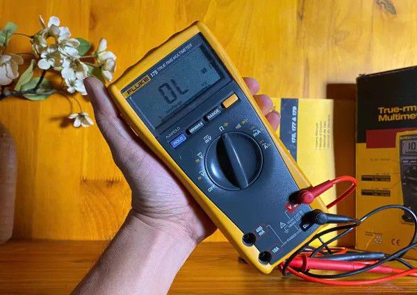
Practical Fluke 175

Step-by-Step Guide to Measuring Voltage and Resistance with the Fluke 175 Multimeter

Measuring DC voltage with the Fluke 175

First, turn the rotary switch to the V-DC mode (straight line symbol). Plug the red test lead into the VΩ jack, and the black lead into the COM jack. Next, touch the probes to the two points to be measured. For a car battery, the screen will instantly display 12.4V.

Measuring AC voltage with the Fluke 175

Switch the dial to V-AC (wave symbol ~). The Fluke 175 True RMS reads accurately even with distorted waves from motors. When measuring a household outlet, the standard is 220V. If it fluctuates between 210-230V, you should call an electrician to check the power grid. The bar graph on the Fluke 175 updates quickly, helping you monitor changes immediately.

Measuring resistance with the Fluke 175

Turn off the circuit's power, then turn the dial to Ω, plug the probes in just like when measuring DC. Touch the probes to the component; a 1kΩ resistance will appear correctly on the screen, with an error margin of only 0.9%. When modifying an amplifier, a speaker will typically show an 8Ω resistance. If it reads infinity (OL), the reason is usually a broken wire. A beep sound will notify you of an open circuit that needs immediate repair. For safe use, you should use the TL75 test leads included with the Fluke 175, which have a load capacity of up to 1000V.
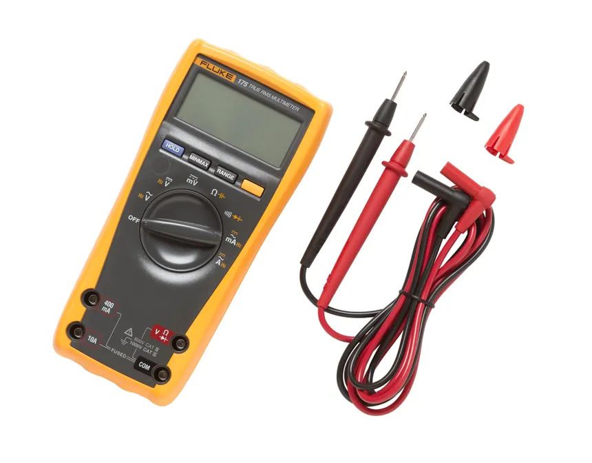
Combo Fluke 175 + TL75

Read more:

Top Mini Multimeters of 2026: Extremely Convenient, Great Value for Money - What You Need to Know

Testing the heating resistance with a multimeter is easy to understand.

Tips for measuring 220V current with a multimeter that not everyone knows

What are some alternatives alongside the Fluke 175?

If you want to look deeper, you can refer to the Fluke 177 and Fluke 179 multimeters. First, the Fluke 177 and 179 add a backlight and Min/Max/Avg features. The Fluke 175, Fluke 177, and Fluke 179 are all CAT III 1000V rated, but the Fluke 179 is better suited for harsh environments. If your budget is tight, you can start with the Fluke 175 and gradually upgrade to higher versions. Research from NIST emphasizes that features like True RMS on the Fluke 175 help provide measurements that are over 20% more accurate compared to others in the same price range.
관련 뉴스

Which products are tested using a -40°C to +150°C thermal shock chamber?
2026년 07월 22일 14시 45분 25초

Automotive circuit boards, sensors, modules, and plastic components can all experience issues after repeated transitions between cold and hot environments. A thermal shock chamber operating from -40°C to +150°C enables the replication of these temperature fluctuations under controlled testing conditions.

Does thermal shock cause damage to electronic components?
2026년 07월 22일 10시 40분 49초

An electronic component may operate stably under constant temperature conditions yet fail after repeated rapid transitions between hot and cold. The issue typically stems not from a specific temperature level, but rather from the rate of temperature change and the number of hot-cold cycles

The rigorous standards behind a multi-million-dollar MRI suite
2026년 07월 21일 14시 54분 01초

An MRI system may be correctly installed and fully connected to the power supply, yet still encounter issues if the surrounding environment fails to meet technical specifications. Electromagnetic interference, RF shielding, power quality, grounding, temperature, humidity, and particulate levels are all factors that may require assessment, depending on the facility's design and the manufacturer's requirements.

Sinusoidal and Random Vibration: A Test Setup Guide for Industrial Engineers
2026년 07월 21일 10시 30분 38초

During the operation of industrial machinery or the transportation of goods, persistent mechanical vibrations inevitably occur; these are a primary cause of material fatigue, loosened connections, and cracking in printed circuit boards (PCBs). To ensure product integrity before delivery to customers, R&D and QA/QC engineers must simulate these dynamic forces using vibration test systems.

Capacities of laboratory centrifuge tubes
2026년 07월 20일 13시 55분 40초

Tubes with capacities of 0.2 ml, 1.5 ml, 15 ml, or 50 ml are commonly found in laboratories, yet each type is associated with specific sample categories and equipment configurations. DNA and RNA samples typically require small-volume microtubes; blood and cell samples often utilize 5 ml or 15 ml tubes; while large-volume processing workflows may require tubes of 50 ml, 100 ml, or greater capacity

혜택 소식 받아보기

대량 할인, 도매 가격 업데이트 및 신제품 소식을 이메일로 받아보세요.

구독하면 당사의 서비스 이용약관개인정보 처리방침에 동의하는 것으로 간주됩니다.

빠른 지원

인증된 전문가에게 직접 연결