For full functionality of this site it is necessary to enable JavaScript.
EMIN.VN
0

Reliability Test for Relay Using GW PSW Power Supply and PEL-3111 E. Load

2017년 12월 19일 17시 28분 24초

How do you conduct relay connection point (N.O. / N.C.) tests? How do you test the life cycle of relay’s connection point (N.O. / N.C.)?   How do you evalua

How do you conduct relay connection point (N.O. / N.C.) tests? How do you test the life cycle of relay’s connection
point (N.O. / N.C.)?   How do you evaluate the connection resistance of connection point (N.O. / N.C.) after multiple
tests? How do you evaluate the speed for operating connection point (N.O. / N.C.)? 

Relay, functioning to produce mechanical on-off movement by receiving electric signal to change electro magnet,
is often applied to control other electronic device via receiving electronic signal. Voltage exerted on relay’s coil
allows current to pass through coil and magnetizes core. Armature is then be pulled by core due to electromagnetic
force. Hence, a mechanical on-off movement is produced.  


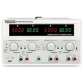
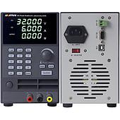
As shown on the top diagram, PSW 30-108, Relay and PEL-3111 are connected by series. PEL-3111 is set to 80A
current sink. Each time, Relay’s NO-COM is closed, NO-COM is tested for its current reliability. In the meantime,
PSW 80-40.5 is utilized to output sequential power supply to produce control signal to control Relay’s NO-COM.

One GW Instek PSW 80-40.5 can meet the actual measurement requirements via planning Relay’s control signal.
It not only controls signal’s voltage, current, time and period, but also determines the number of operating cycle.
There are totally 20,000 steps and each step can be set from 50ms to 20 days. The number of cycle can reach
1 billion or infinite by different specifications. Relay’s control signal can only verify the mechanical characteristics
of NO-COM and NC-COM. For further electric characteristic verification of NO-COM and NC-COM, PSW 30-108
and PEL-3111 must be concurrently utilized to produce C.C. output. Based upon Relay’s specifications, the combined
application of two instruments can conduct fast current switching test and provide large current verification,
including current withstanding value and current withstanding time so as to ensure Relay’s quality. 
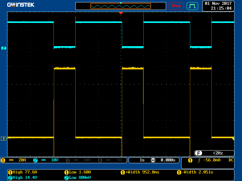
GW instek PEL-3111 Programmable DC Electronic Load (150V, 210A, 1050W)

관련 뉴스

EMIN Becomes an Official Distributor of ZEISS in Vietnam Starting July 2026
2026년 07월 24일 15시 35분 27초

Starting in July 2026, EMIN officially became an Authorized Distributor of ZEISS in Vietnam. With a history spanning more than 175 years, ZEISS is recognized as one of Germany's technology companies and a global pioneer in the fields of optics and optoelectronics. The company provides advanced solutions for industrial manufacturing, scientific research, healthcare, semiconductor production, and quality assurance.

How Does Fluke Help Factories Detect Hard-to-Spot Electrical Risks?
2026년 07월 24일 14시 23분 04초

The more high-capacity machinery a factory houses and the more complex its power supply network becomes, the harder it is for routine checks such as voltage measurements or visual inspections of electrical cabinets to fully reflect the safety status.

Which products are tested using a -40°C to +150°C thermal shock chamber?
2026년 07월 22일 14시 45분 25초

Automotive circuit boards, sensors, modules, and plastic components can all experience issues after repeated transitions between cold and hot environments. A thermal shock chamber operating from -40°C to +150°C enables the replication of these temperature fluctuations under controlled testing conditions.

Does thermal shock cause damage to electronic components?
2026년 07월 22일 10시 40분 49초

An electronic component may operate stably under constant temperature conditions yet fail after repeated rapid transitions between hot and cold. The issue typically stems not from a specific temperature level, but rather from the rate of temperature change and the number of hot-cold cycles

The rigorous standards behind a multi-million-dollar MRI suite
2026년 07월 21일 14시 54분 01초

An MRI system may be correctly installed and fully connected to the power supply, yet still encounter issues if the surrounding environment fails to meet technical specifications. Electromagnetic interference, RF shielding, power quality, grounding, temperature, humidity, and particulate levels are all factors that may require assessment, depending on the facility's design and the manufacturer's requirements.

혜택 소식 받아보기

대량 할인, 도매 가격 업데이트 및 신제품 소식을 이메일로 받아보세요.

구독하면 당사의 서비스 이용약관개인정보 처리방침에 동의하는 것으로 간주됩니다.

빠른 지원

인증된 전문가에게 직접 연결