For full functionality of this site it is necessary to enable JavaScript.
EMIN.VN
0

sfs

2026년 11월 06일 16시 40분 32초

dsd

RF measurements distorted, or afraid of burning the probe? When to switch to a signal analyzer

RF measurement

Input overload errors distort RF measurements and can damage probes. Learn the causes, how to spot them, and how to choose the right Keysight N9000B, N9010B or FieldFox signal analyzer at EMIN.
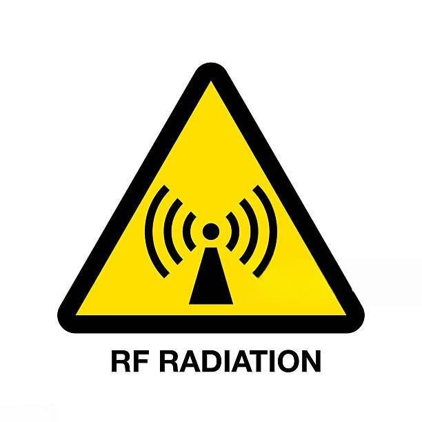
Input overload
The problem
A signal that is too strong saturates the input stage. The result is distorted but still looks clean.
Quick test
Add 10 dB of input attenuation. If the harmonics change with it, the distortion comes from the measurement.
What to do
Use a signal analyzer with built-in attenuation, and pick the series by where you work: lab or field.

01What is an input overload error, and what does it look like on screen?

Some weeks, an RF engineer spends the whole week hunting a fault in an amplifier circuit. The waveform on the oscilloscope is flat-topped, the spectrum shows a string of strange harmonics, and the noise floor has crept up compared with yesterday. The circuit is suspected first, then the layout, then the power supply. Then someone lowers the input power, the harmonics disappear, and the problem turns out to be the measurement, not the circuit.

That is the price of an input overload error: a quiet fault that costs more time and money than many people expect.

Every probe and every measurement port has a linear working range. When the incoming signal is stronger than that, the input buffer stage starts to saturate. Imagine listening to someone talk normally, and then someone shouts in your ear. Your ear does not just hear wrongly, it also rings for a while. The input circuit of an instrument reacts the same way: it no longer reproduces faithfully what is fed into it.

Sign 1
Clipped waveform
Peaks flatten because the input stage saturates.
Sign 2
False harmonics appear
Harmonic components show up that the circuit does not really produce.
Sign 3
Noise floor rises
Small signals get buried.
The danger is that the result still looks clean, so it is easy to trust. In severe cases, especially with high-frequency active probes, the internal amplifier stage can fail completely, and repair or replacement is not cheap.

02Why is adding an external attenuator still not a complete fix?

The usual reflex of engineers is to put an external attenuator in front of the input. This helps, but there are two easy places to trip.

Pitfall 1
Compensation factor
If you forget to add the attenuation value to the measurement, the amplitude reading is off, and nothing warns you.
Pitfall 2
Mechanical
Every extra adapter at high frequency adds insertion loss and reflections, so the data can be off even when every number on screen looks reasonable.

03How does a signal analyzer solve this?

A signal analyzer is designed to take the RF signal straight from its connector, with the input attenuator built into the instrument. This attenuator is tied to the reference level the engineer sets, which keeps the input mixer in its linear range and limits distortion created by the measurement itself.

Combined with a wide dynamic range, the analyzer lets you see a strong signal and a very weak one side by side without saturation. In the frequency domain, engineers can also measure nonlinear distortion figures directly, such as the 1 dB compression point and the third-order intercept (TOI), which ordinary probes do not show.

Note 1. Internal attenuation is a layer of protection, not armor. Every analyzer still has a maximum allowed power at its input port, listed in the manufacturer's documentation. When the source is strong, add an external attenuator.
Note 2. The 10 dB test. To tell real harmonics from harmonics the instrument generates itself, add 10 dB of input attenuation. If the harmonic components change with it, most of them come from the measurement itself, not from the circuit.
The 10 dB test in two cases
Clean circuit, harmonics generated by the analyzer
Added attenuation2nd harmonic3rd harmonic
+0 dB
−30 dBc
−20 dBc
+10 dB
−40 dBc
−40 dBc
+20 dB
−50 dBc
−60 dBc
Harmonics drop sharply as attenuation is added. The distortion comes from the measurement, not the circuit.
Real circuit with harmonics near −45 dBc
Added attenuation2nd harmonic3rd harmonic
+0 dB
−30 dBc
−20 dBc
+10 dB
−39 dBc
−39 dBc
+20 dB
−44 dBc
−45 dBc
Harmonics level off near −45 dBc despite more attenuation. The distortion comes from the real circuit.
Illustrative figures with a +5 dBm source. Not a substitute for the manufacturer's documentation.

04Designing 5G or IoT circuits in a lab: which series should you look at?

For labs and R&D teams that need a close look at spectrum and modulation, the Keysight N9000B, N9010B EXA and N9021B MXA benchtop series are the first to consider. What they share is good dynamic range management and a low noise floor, ideal when you need to inspect small signal components without the measurement adding distortion.

Benchtop
Keysight N9000B
Signal analyzer series for the lab.
View product →
Benchtop
Keysight N9010B EXA
Good dynamic range, low noise floor.
View product →
Benchtop
Keysight N9021B MXA
Inspect small components without adding distortion.
View product →

05Working in the field and climbing towers to test sites?

In the field, what you need most is a compact, rugged instrument that measures directly at the connector instead of carrying probes and many cables. The Keysight FieldFox series suits this kind of work. Depending on model and options, one handheld unit combines spectrum analysis, cable and antenna analysis (CAT) and network analysis (VNA).

Frequency coverage runs from the N9916A at 14 GHz and N9917A at 18 GHz up to the N9952A at 50 GHz, so you can choose by the real band of the antenna system and cable run you are testing.

N9916A
14 GHz
N9917A
18 GHz
N9952A
50 GHz
In one unit
Spectrum analysis
In one unit
Cable and antenna analysis (CAT)
In one unit
Network analysis (VNA)

06For specialized radio and cable TV, what does EMIN suggest?

For the specific needs of radio communications, EMIN offers Astronics instruments such as the R8000C, R8100 and R8200. For cable TV systems, the Promax CABLE RANGER is an option for monitoring and assessing signals along the line. These series are built for exactly this kind of work, so operation and display follow the needs of people working on transceiver stations and cable networks.

Astronics
R8000C
Radio communications.
View product →
Astronics
R8100
Radio communications.
View product →
Astronics
R8200
Radio communications.
View product →
Promax
CABLE RANGER
Monitor and assess signals on the cable line.
View product →

07Before you buy, which factors matter more than price and frequency range?

Maximum frequency and price are the two most visible numbers, but they are not enough to decide.

RBW
Resolution bandwidth
Shows how closely spaced signals you can separate.
Noise floor
Displayed noise floor
Decides how weak a signal you can see.
Software
Software expandability
Shows whether the analyzer can keep up with new modulation standards over the next few years.
Use case
Lab or field
Decides the size, durability and handling of the instrument.

A small habit that saves a lot of trouble: estimate the peak power of the source before connecting, and compare it with the maximum allowed at the input port. It takes under a minute, and you get a trustworthy measurement and an undamaged instrument.

Checklist before you connect
☐Estimate the peak power of the source
☐Compare it with the maximum input level in the manufacturer's documentation
☐Strong source: add an external attenuator
☐Add the external attenuation value to the measurement offset
☐See odd harmonics: add 10 dB of input attenuation to test

Where to get advice on the right frequency range and attenuator setup?

Every RF application has its own challenge in power, frequency band and test environment. The EMIN engineering team is ready to hear about your signal source and measurement goal, then propose a sensible setup, including attenuators and accessories. Contact EMIN by hotline or email for advice and a quote.

Browse signal analyzers

관련 뉴스

Common Types of Electric Screwdriver Bits and How to Choose the Right Bit for Each Type of Screw
2026년 11월 06일 15시 02분 34초

A set of screwdriver bits typically contains dozens of pieces, each with a distinct shape. Every shape is designed to fit a specific type of screw recess; using the wrong bit can cause it to slip or damage the screw head—a risk that is especially high when using high-speed electric screwdrivers. This article introduces common types of electric screwdriver bits, explains how to distinguish between those that are easily confused, and outlines the key specifications to consider when making a purchase

Battery Simulator vs. Power Supply: Which Should You Use?
2026년 11월 06일 14시 40분 32초

Choose a battery simulator when a device must be tested against changing battery behavior, resistance, or fault conditions. Choose a DC power supply when stable, controllable power is sufficient.

What Is a Bidirectional DC Power Supply Used For?
2026년 11월 06일 14시 39분 44초

Bidirectional DC power supplies support two-way energy flow. Their main uses include EV and component testing, renewable energy storage, microgrids, and R&D validation of power equipment.

How Does Battery Cycle Life Testing Work with a Bi-Directional DC Supply?
2026년 11월 06일 14시 37분 49초

Battery cycle life testing repeatedly charges and discharges a cell under defined current, voltage, temperature, and rest conditions. A bi-directional DC supply can both source and sink current, while periodic Reference Performance Tests track capacity and DC internal resistance over time.

Testing Experience at Tektronix Semiconductor 2026
2026년 11월 06일 13시 44분 10초

At the Tektronix Semiconductor 2026 seminar, alongside technical presentations on semiconductor technologies, attendees had the opportunity to explore and experience live equipment demonstrations featuring the DPO1000, Keithley 4200A-SCS, MSO58B, and EA-PSB 10000 bidirectional DC power supply. Each instrument serves a different measurement purpose, illustrating key technical requirements in semiconductor research and device validation.

혜택 소식 받아보기

대량 할인, 도매 가격 업데이트 및 신제품 소식을 이메일로 받아보세요.

구독하면 당사의 서비스 이용약관 및 개인정보 처리방침에 동의하는 것으로 간주됩니다.

빠른 지원

인증된 전문가에게 직접 연결