What is a Power Factor Correction Capacitor?
A power factor correction capacitor (often referred to simply as a "PFC capacitor") is a device integrated into electrical circuits to compensate for reactive power, thereby improving the power factor and helping to avoid additional costs caused by violations of electricity usage regulations in Vietnam.
Despite being a common device in the electrical field, many people still wonder what a power factor correction capacitor actually is and how to effectively utilize its functions in practice. In reality, “tụ bù” is just a familiar term in Vietnamese, and it may also be referred to as a power capacitor, electric capacitor, or reactive power capacitor—all of which refer to the same type of device.
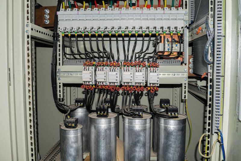
Scientifically, a PFC capacitor is a system consisting of two conductive plates placed close to each other, separated by an insulating material called a dielectric. This device can store and discharge electrical energy during the operation of a circuit. To charge the capacitor, the two plates are connected to a power source—one to the positive terminal (storing positive charge) and the other to the negative terminal (storing negative charge).
The ability of a capacitor to store charge at a given voltage is measured by a quantity called capacitance. Capacitance is defined as the ratio of the charge stored on the plates to the voltage across them. This is a key parameter that reflects the effectiveness of the capacitor in an electrical circuit.
Structure of a Power Factor Correction Capacitor
These capacitors are typically constructed as oil-immersed paper capacitors, designed to withstand high temperatures and provide excellent insulation. Inside, there are two electrodes made from thin aluminum strips, interleaved with special insulating paper. This entire component is enclosed in a sealed metal casing to prevent moisture and dust from entering. The two terminals are extended outside for direct connection to the electrical system.
Operating Principle
During the transmission of electric power from the source to the load, two types of power occur simultaneously: active power and reactive power. Active power performs actual work to operate equipment, while reactive power does not produce useful work but increases the load on the electrical system.
Using power factor correction capacitors compensates for reactive power, thereby increasing the power factor (cosφ), reducing losses, and improving overall energy efficiency. These power quantities are related by the following formulas:
P = S × cosφ
Q = S × sinφ
S² = P² + Q²
Where:
S is apparent power,
P is active power,
Q is reactive power.
A higher cosφ indicates a more efficient system where a greater proportion of electrical energy is converted into useful work. With PFC capacitors in the system, part of the reactive power is automatically balanced, reducing the burden on the power source and optimizing active power usage.
Classification of Power Factor Correction
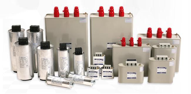
PFC capacitors are classified based on two main criteria: internal structure and operating voltage. Depending on the specific application, users choose the appropriate type to meet technical requirements and ensure system stability.
By Voltage
Three-phase capacitors (commonly 415V or 440V) for industrial use:
Single-phase capacitors (typically rated at 230V or 250V) for residential or small-load systems.
415V capacitors are suitable for 380V systems—widely used in industry.
440V capacitors are designed for higher voltage systems, especially where harmonics or voltage fluctuations are present. These are often used with harmonic filters to improve effectiveness and protect equipment.
Do Power Factor Correction Capacitors Save Electricity?
In both industrial and residential electrical systems, many devices such as electric motors, transformers, and HVAC systems operate on induction principles. This results in the consumption of both active power (P - kW) and a significant amount of reactive power (Q - kVAr). The presence of reactive power increases the total apparent power (S - kVA), leading to line losses, lower transmission efficiency, and greater risk of overload and voltage drops.
The power factor (cosφ) is a measure of energy usage efficiency. A low cosφ indicates high reactive power consumption, reducing energy efficiency. Electricity regulations typically require a minimum power factor of 0.9. If the system operates below this level, users may incur fines for excessive reactive power usage.
Installing PFC capacitors reduces the reactive power drawn from the grid, improving cosφ (commonly set to around 0.95). This not only helps avoid fines but also reduces the burden on the transmission system, extends the lifespan of equipment, and saves costs on infrastructure like cables, transformers, and protection devices.
Thus, using power factor correction capacitors not only enhances the efficiency of the electrical system but also brings clear economic benefits to operators.
Purpose of Using PFC Capacitors in Electrical Systems
In any electrical system—from factories to commercial centers—PFC capacitors play a quiet but vital role. Their primary purpose is to compensate for reactive power, which makes the system operate more efficiently. As a result, the power factor (cosφ) is significantly improved. This is a key factor in avoiding penalties from electricity providers and reducing monthly electricity bills.
Additionally, installing PFC capacitors reduces the load on cables, minimizes voltage drops, improves the transmission capacity of the system, and enhances the performance of transformers. In capacitor panels, besides the capacitors themselves, auxiliary components like controllers, circuit breakers, contactors, meters, and even harmonic filters are included in systems with high harmonic content—to ensure safety, stability, and smart operation.
How to Install Power Factor Correction
Not all facilities should install PFC capacitors the same way. The most effective approach is always the one that fits the scale of electricity usage and load characteristics of the facility.
For Small Facilities
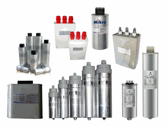
Small workshops or businesses that don’t use equipment producing large harmonic content usually have low reactive power and modest electricity use. In some cases, they may not be fined for a low power factor. However, if cost savings are desired, installing a static capacitor panel is a compact, simple, and low-investment solution.
A typical static capacitor panel includes: a small enclosure (around 500x350x200mm), a circuit breaker, and a small capacitor (2.5–10 kVAr). This setup suits locations aiming to reduce electricity costs without needing high automation.
For Medium-Sized Facilities
Facilities with medium electricity consumption and stable continuous loads almost always need PFC capacitors to avoid fines and save electricity. The recommended solution is a multi-stage capacitor panel, which comes in two forms:
Manual capacitor banks: Capacitors are switched on/off manually. Simple, but less flexible, error-prone, and time-consuming.
Automatic capacitor banks: The optimal choice—automatically measures and switches capacitor stages via a controller. Accurate, time-saving, and protective for equipment.
A standard automatic capacitor panel includes: a cabinet (1–1.2m high), a controller with 4–14 stages, a main breaker, individual stage breakers, contactors, voltage/current meters, phase indicators, etc.—all designed for synchronized operation to prolong capacitor life and ensure system stability.