What is an dial indicator ?
Dial indicator is commonly used in the mechanical processing industry. This device is usually attached to the head of a high gauge, helping to measure the straightness, reorientation of the inner surface or parallelism of the groove.
In addition, the dial gauge is also used to check plane, perpendicularity and deviation, especially useful in the fields of construction, industry and mechanical engineering. With high sensitivity and extremely low error, the meter ensures accuracy from 0.01mm to 0.001mm, meeting strict measurement requirements..
What Can a Dial Indicator Measure?
A dial indicator is primarily used to detect and determine deviations of a component from a reference position or datum. It is not intended for measuring absolute dimensions like a caliper or micrometer. Instead, it is most effective for detecting very small displacements and geometric deviations.
Measuring Runout of Shafts and Round Components
When the contact tip touches the outer surface of a shaft and the component is rotated, the dial indicator needle moves according to variations in the surface. The difference between the highest and lowest readings can be used to determine radial runout.
This method is commonly used to inspect shafts, bushings, flywheels, chucks, and other round components after machining.
Checking Flatness and Straightness
The contact tip can be moved across the surface being inspected to record variations at different positions. If the needle fluctuates, the surface has differences in height relative to the reference line or plane.
For machine tables, work surfaces, guideways, and other precision-machined surfaces, a dial indicator provides a quick way to identify high and low points and determine the deviation between different locations.
Checking Parallelism
When one surface is selected as the reference, the dial indicator can be moved across a second surface. The change in readings between different positions indicates the relative deviation between the two surfaces.
This method is commonly used to check machine tables, fixtures, mating surfaces, and other surfaces that need to maintain a relatively consistent distance from a reference.
Checking Perpendicularity
A dial indicator can be used together with a surface plate, precision square, or fixture to check the perpendicular relationship between two surfaces. As the contact tip moves along the surface, changes in the indicator reading show the deviation from the reference.
This is a geometric inspection rather than a direct measurement of an angle in degrees.
Checking Concentricity and Relative Position
When checking whether cylindrical surfaces share a common axis or determining the relative position between components, a dial indicator can be used with a fixture and a rotating reference. As the component rotates, needle movement provides data for evaluating the deviation.
The measurement datum must be clearly defined before determining concentricity, because runout and concentricity are two different geometric characteristics.
Checking Play and Small Displacements
A dial indicator is also useful for detecting abnormal movement in mechanical assemblies. By applying a controlled force to a component, the resulting needle movement can be used to evaluate play in bearings, transmission mechanisms, or assembled components.
For this type of measurement, the applied force must be controlled. If the force varies between measurements, the readings may change even when the condition of the mechanism remains the same.
Checking Position During Machine Alignment
During the installation and maintenance of machine tools, dial indicators are commonly used to align components or machine assemblies to the correct position. The operator monitors the needle movement while making adjustments until the deviation falls within the specified tolerance.
Therefore, the value of a dial indicator lies not only in the displayed reading but also in its ability to provide a direct visual indication of positional changes. This makes it particularly useful for mechanical alignment, fixture inspection, and machine setup.
What is the structure of a watch?
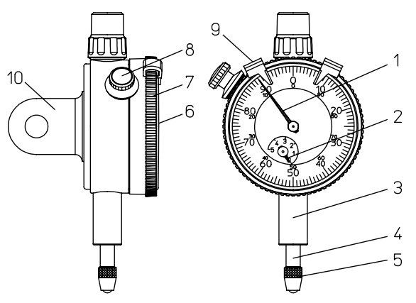
The structure of the mechanical dial indicator is quite simple, similar to many other types of gauges, including the following main parts:
- Measuring head: This part is in direct contact with the surface to be tested, usually made from abrasion-resistant alloy to ensure durability and accuracy.
- Measuring axis: The length of the measuring axis varies depending on the type of dial indicator, to accommodate the inspection of details of different sizes.
- Bushing: This part protects part of the measuring shaft, ensuring smooth and durable operation.
- Transmission mechanism: This is a system that includes transmission linkage details, helping the measuring shaft move and displaying results. With mechanical watches, measurement results are expressed through the movement of the index needle, while electronic watches use a sensor system to process and display measurement data.
- Outer shell: Protects the internal components, making the device effectively dust and water resistant.
In addition, the dial gauge is also equipped with other details such as clamping lever, locking screw, cover, depending on the design of each type.
Working principle of dial indicator
The operating principle of the dial indicator is quite simple. When the main axis of the watch moves, it will transmit a signal to the scale, helping the indicator needle on the watch face display the measured value. The mechanism operates based on a combination of pre-set gears, ensuring accuracy during measurement.
How to use the dial indicator
To use the dialer effectively and simply, you can do the following steps:
1. Prepare a meter, the object to be measured and a suitable space to perform the measurement.
2. Check the watch's operating status to ensure the device is still working well.
3. Fix the meter to the object to be measured on the stand, then adjust the display ring on the scale to 0 before starting to measure.
4. Bring the object to be measured into contact with the meter's measuring head and read the value displayed on the dial. To ensure accuracy, measurements should be performed 1-3 times.
Note: When measuring, make sure the displayed indicators are stable. When dropping or lifting the measuring shaft, be careful to let the shaft fall naturally. Measurement results should not differ by more than 0.5 bars to ensure accuracy.
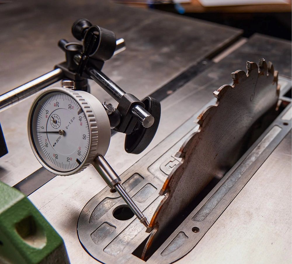
How to read numbers on a dial indicator
Reading the numbers on the dialer is simple thanks to the device's intuitive design.
For electronic dial indicator, the numbers are displayed directly on the LCD or LED screen, making it easy for users to observe. However, due to its ability to quickly update data, this type of meter can be difficult when checking small changes on a flat surface.
For mechanical dials, when moving the measuring position, the indicator needle on the watch face also moves accordingly, helping users observe changes more clearly.
Specific reading is as follows:
The small scale displays the integer mm, read based on the position of the index needle.
The large scale displays the percentage of mm, determined by the position of the pointer on the large graduation ring.
For example: With a dial indicator with 0.01mm division, if the needle is at the 2nd mark on the small ruler and the 25th mark on the large ruler, the measurement result is 2.25mm.