Setting an MPO test reference establishes a 0 dB baseline that removes the loss of the test reference cords (TRCs) from subsequent measurements. This is necessary to measure fiber-link insertion loss while retaining the loss of the link’s first and last connectors.
For fiber optic attenuator meter, prepare the units and cords first, then use the Set Reference Wizard to set and verify the reference. A changed setup, disconnected output-side TRC, or questionable result requires renewed attention to the reference.
Summary: A reference removes TRC loss from the measurement baseline. Warm up the main and remote units for at least 15 minutes, inspect connector end faces before mating, and do not disconnect the red TRC output branch after referencing. Verify TRC condition before testing and re-establish the reference when the setup changes.
Why must an MPO test reference be set before insertion-loss testing?
An MPO test reference prevents TRC loss from distorting insertion-loss results. TRCs connect the main and remote test units to the link, so their loss must be referenced out at 0 dB before measuring the device under test.
The first and last connectors belong to the live fiber link and should remain part of the total link measurement. Since a single connector cannot be measured in isolation, the end connectors are measured as a mated pair.
When should the MPO test reference be reset?
Reset the reference whenever the test configuration or output-side TRC connection changes. Continuing with an invalid reference can affect every later result.
- After changing an input module for a different test setup.
- After disconnecting a TRC from a tester output port, even if it is reconnected.
- When measurements show excessively negative loss, which can indicate contamination or insufficient warm-up.
- When several hours have elapsed since setting the reference, because cords can become contaminated or drift and a tester may have powered off.
Note: The source information states that CertiFiber™ Max displays elapsed time since the reference was set and the time between tests. These indicators can help determine when to review the setup.
What should be prepared before setting the reference?
Turn on both the main and remote units and allow them to warm up for at least 15 minutes. More time may be needed when the units begin above or below ambient temperature; referencing a cold tester can contribute to inaccurate negative-loss results.
Select the applicable test parameters before opening the wizard. Available setup considerations include connector type, pinned or unpinned configuration, fiber type, polarity, number of connections, test limit, and reference method. The source describes the 1-jumper reference method as the default method normally used.
Inspect the end faces of TRCs, verification cords, and the device under test immediately before mating. Clean and reinspect when necessary; even new cords may be contaminated.
How do TRC color branches connect during MPO reference setting?
The Y-cable TRCs for CertiFiber™ use color coding that corresponds to tester ports. This coding is described as the same for traditional MPO and MMC very small form factor (VSFF) input connectors.
| TRC branch color | Connection role |
|---|---|
| Red | Connects to the red 16-fiber MPO output, or source, port. |
| Yellow | Connects to the fiber link being tested and is used during the reference workflow. |
| Black, grey, or white | Connects to the input, or meter, port. Black is for 12 fibers, grey for 16, and white for 24. |
What is the Set Reference Wizard workflow for CertiFiber™ Max?
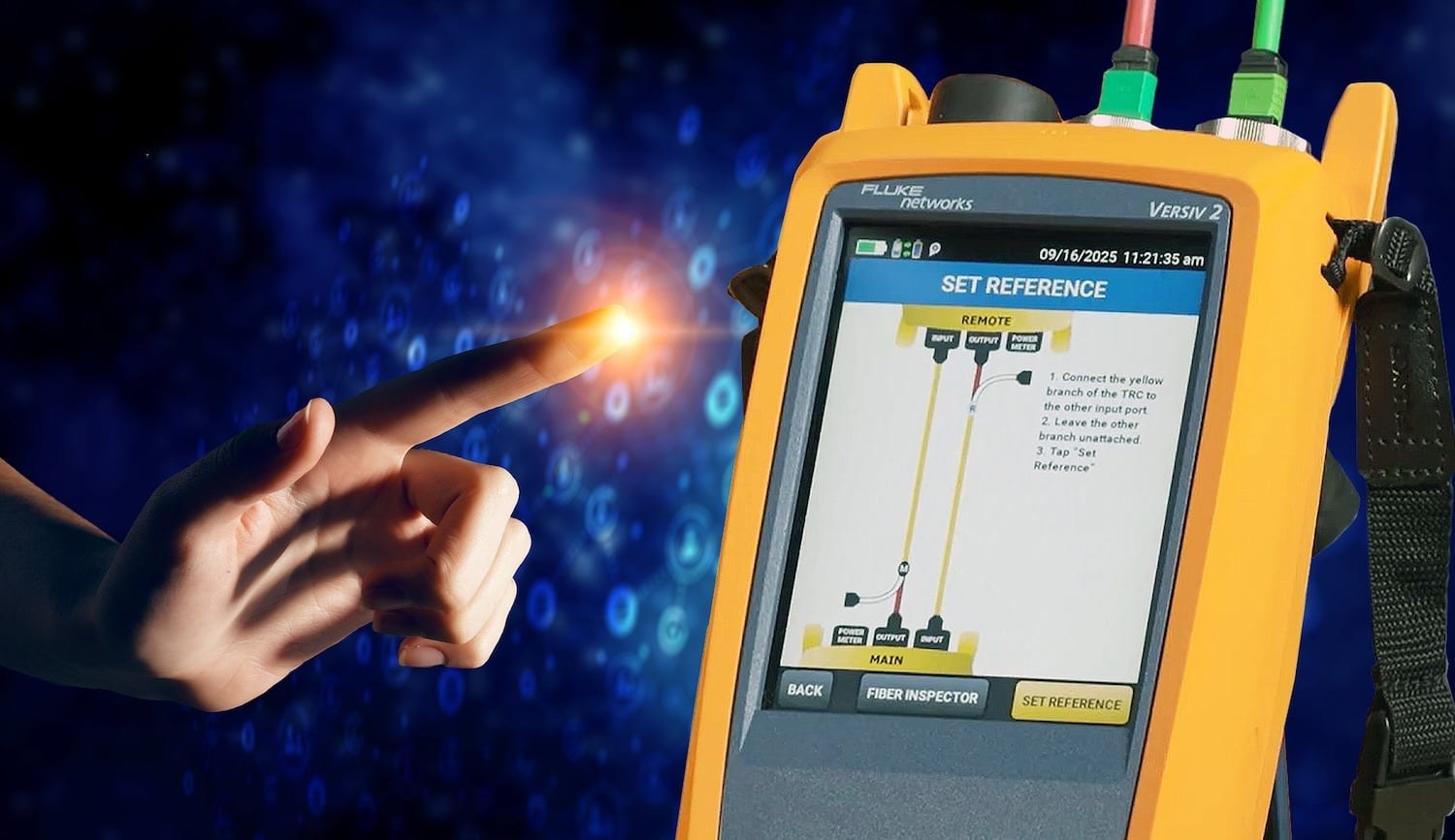
The Set Reference Wizard lists the required input modules, TRCs, and verification cord based on the selected configuration, then uses color-coded guidance to set and verify the reference.
- Connect the red output branches of the TRCs to the red output ports on the main and remote units.
- Connect the yellow branches to the input ports on both units, then set the reference.
- Remove the yellow branches from the input ports and connect them to the verification cord.
- Connect the receive branches—black, grey, or white—to the input ports on the main and remote units.
- Verify TRC performance and review the displayed result and date/time-stamped ID.
Do not disconnect the red TRC branch from the output port after the reference is set. Disconnecting it changes the power level entering the fiber and invalidates the reference. After the receive branches are connected, only the yellow branch should be handled in this workflow.
What should be done if TRC verification is outside the expected range?
If the verification result is outside the expected range, reinspect and clean the TRC, verification cord, and tester output port, then restart the procedure. This response addresses possible contamination at the relevant fiber interfaces.
Once the reference is set and the TRCs pass verification, replace the verification cord with the actual fiber link for testing. The source also states that TRCs may be re-verified during testing; its typical recommendation is verification every 288 tests, while Fluke CertiFiber can track test count and support custom TRC test-count limits.