When plugged in and the electric welding machine does not show any signs of operation such as no output voltage, fan not working, signal light not on, display screen off,... then you should check if the device is experiencing a 24V power failure.
Instructions for checking electric welding machine when 24V power is lost
To start, use a multimeter and set it to the X10 or X1 scale depending on your testing needs.
Measure the power cord and switch in turn. Note: when testing the switch, setting the meter to the X1 scale will help you get more accurate results. If after testing, these components are still working properly, move on to the step of testing the rectifier diode.
For the rectifier diode, if both needles go up or only one end shows resistance, it means the diode is broken. Conversely, if the multimeter shows nothing at both ends, this component is still fine.
Then, power up the machine, turn on the switch and continue to check the 300V high voltage source. At this time, adjust the multimeter to the 1000V scale, then measure between the yellow wire (positive pole) and the red wire (negative pole). If the meter shows about 300V, the source is still working.
In the case of a 300V source, the power cord, switch and diode are still working well, the next step is to evaluate the condition of the power block. Turn the meter to the X10 scale, place the black needle on the middle pin and the red needle on the left pin. If the needle does not move, the power is still working; if the needle jumps, the power is damaged and needs to be replaced.
If the power circuit is still working, we move on to checking the 24V power source. First, remove the 300V power board, disconnect the fan wire and transformer, and remove the 24V power connector. At the same time, discharge the remaining charge in the 475 capacitor to ensure the highest measurement accuracy.
Next, check the power, output pulse diode, and trigger resistor. With the trigger resistor, you should remove it from the circuit for more accurate measurement. For example, if you find that the trigger resistor has stopped working, you need to replace this component before continuing to check other parts.
Before replacing the starter resistor, you need to make sure that the replacement part is still usable. Carefully check the value and operating status of the new resistor. If it meets the requirements, cut off the excess leg with pliers and use a soldering iron to solder the resistor to the correct position on the circuit board.
After installing the starter resistor, re-supply the 300V power supply. At this time, if the welding current display turns on again, it means that you have successfully handled the 24V power loss error on the soldering iron. Then, continue to reconnect the fan wire and the power transformer, when you hear the fan running, the system has basically recovered.
To confirm more firmly, adjust the multimeter to the 250V scale, use the red probe to check the output voltage. Hold the black probe with the other hand and leave the ground foot. If the meter shows a voltage reading between 60 and 70V, it shows that the welder is operating normally again.
If the 24V power supply is fluctuating or experiencing unstable startup, an oscilloscope can help to more clearly observe the switching pulses and startup process of the power supply at the switching power source and DC bus. Direct measurement of the high voltage should be avoided unless the measurement point and safety method have been clearly identified.
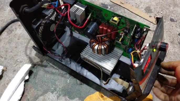
How to fix the problem of electric welding machine losing 24V power
Before replacing the starter resistor, you need to make sure that the replacement part is still usable. Carefully check the value and operating status of the new resistor. If it meets the requirements, cut off the excess leg with pliers and use a soldering station to solder the resistor to the correct position on the circuit board.
After installing the starter resistor, re-supply the 300V power supply. At this time, if the welding current display turns on again, it means that you have successfully handled the 24V power loss error on the soldering iron. Then, continue to reconnect the fan wire and the power transformer, when you hear the fan running, the system has basically recovered.
To confirm more firmly, adjust the multimeter to the 250V scale, use the red probe to check the output voltage. Hold the black probe with the other hand and leave the ground foot. If the meter shows a voltage reading between 60 and 70V, it shows that the welder is operating normally again.
The situation of the electronic welding machine losing 24V power is not too rare and can be completely fixed if checked properly. By using a multimeter to check components such as power cord, switch, rectifier diode, 300V power source, power circuit and especially the primer resistor in the 24V power source, users can quickly determine the cause and repair it effectively. Replacing components must be done carefully and properly to ensure the machine operates stably again. Hopefully the above instructions will help you handle this problem more easily, limit downtime and save maintenance costs.
This guide to troubleshooting 24V power loss applies to stick welding machine, TIG welding machine, and MIG welding machine.
Frequently Asked Questions
There is 300 V DC, but no 24 V. Does this mean the auxiliary power supply has failed ?
Not necessarily. The auxiliary power supply, downstream load, and protection circuit should all be checked.
Can an external 24 V power supply be used for testing ?
Only after confirming the correct voltage, polarity, supply current, and power pins according to the wiring diagram for the specific machine model. Applying power incorrectly can damage the control board.
The startup resistor has been replaced, but the machine still does not power on. What could be the cause ?
The startup resistor is only one part of the startup circuit. The power supply IC, power transistor, capacitors, diodes, pulse transformer, or feedback circuit could also be responsible.
The fan is still running, but the display does not light up. Does this mean the 24 V supply is missing ?
Not necessarily. The fan and control board may be powered by different supply rails. The voltage supplied directly to the control board should be measured.
Is it safe to measure 300 V DC while the machine is powered ?
This should only be performed by a qualified technician. The DC bus capacitor may retain a high voltage even after the power has been disconnected, creating a risk of electric shock through direct contact.