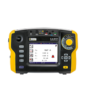
In screen printing, mesh thickness, emulsion thickness, and stencil condition directly affect ink transfer and print sharpness. A screen printing mesh thickness gauge gives printing shops a practical way to monitor these parameters directly on the finished screen, rather than relying only on the material’s nominal specifications.
The PosiTector 6000 FS1 is designed for non-destructive thickness measurements of screen printing mesh, emulsion, stencils, substrates, and dry ink layers. This allows printers to check actual material thickness without damaging the screen or printed surface.

Why thickness matters in screen printing
A typical screen printing process starts with a fine nylon mesh tensioned on a wood or aluminum frame. The mesh receives a light-sensitive emulsion or film. After exposure and washing, the remaining hardened material forms a stencil that defines where ink can pass through the screen.
Ink is pushed through the stencil onto a substrate with a squeegee, then cured. In multicolor work, this sequence is repeated for each required color. Because the mesh and stencil influence how ink is transferred, their thickness is an important process variable.
The thickness of mesh can change during tensioning compared with its original manufacturer-identified thickness. Measuring the screen after it has been stretched at printing tension therefore gives a more relevant value for production control. Mesh thickness is also a factor in formulas used to predict wet ink deposit.
How does the PosiTector 6000 FS1 coating thickness gauge work?
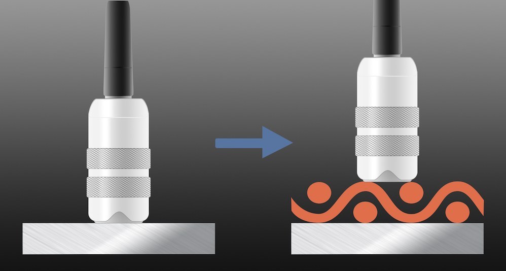
For mesh thickness measurement, the PosiTector 6000 FS1 probe is first zeroed on the supplied ferrous base plate. The screen or substrate is then placed flat against that plate for measurement. The broad probe face spans the mesh openings so the instrument can measure from mesh knuckle to mesh knuckle.
The stated measurement range for the FS is up to 60 mils (1.5 mm), with variable accuracy of 1% and resolution up to 0.05 mil (1 micron). Since mesh surfaces can vary, averaging several readings is a practical way to improve repeatability. Selected models also offer a statistics mode that calculates a running average of readings.
Controlling stencil and emulsion build-up
Stencil build-up refers to the emulsion thickness above the mesh. Monitoring both mesh and emulsion thickness across the screen supports more consistent stencil preparation, particularly where screens are coated manually. The balance is important: insufficient emulsion may not seal adequately, while excessive build-up may affect ink filling and release.
How to measure emulsion over mesh
To measure EOM, or emulsion over mesh, first establish the stretched mesh as the zero reference. Place the metal base plate beneath the uncoated mesh and obtain an average zero value to account for mesh variation. Once the mesh is zeroed, measurements on the coated screen show the emulsion build-up on the stencil.
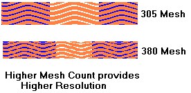
For general non-ultraviolet ink printing and work without extreme detail requirements, the source material notes that an emulsion build-up of about 20% of mesh thickness can provide print resolution and edge definition. This value is described as EMR, or emulsion-over-mesh ratio. The build-up can help lift mesh threads from the substrate surface at the print shoulder, allowing ink to fill the image area.
Fine-detail, multicolor, or ultraviolet printing may use a thinner overall stencil. The source identifies 10% EMR as more common for these applications, where lower total screen thickness can help fine details release without bleeding. These percentages should be treated as process guidance; actual settings depend on the printing application and materials.
Recognizing imbalance in emulsion thickness
If the emulsion layer is too thin, ink may bleed under the stencil and produce rough edges, sometimes described as saw-toothing. Other possible symptoms include smeared images, highlight dot loss, and shadow dot gain.
Excessive emulsion build-up can create a high print shoulder. Ink may fail to fill that area, leaving voids, or may not release properly after filling. When it does release, too much ink can be deposited. Mesh thickness also affects coating needs: thicker mesh generally requires more emulsion to encapsulate it and create a smooth stencil surface, while thinner mesh is usually easier to coat smoothly at a given thickness.
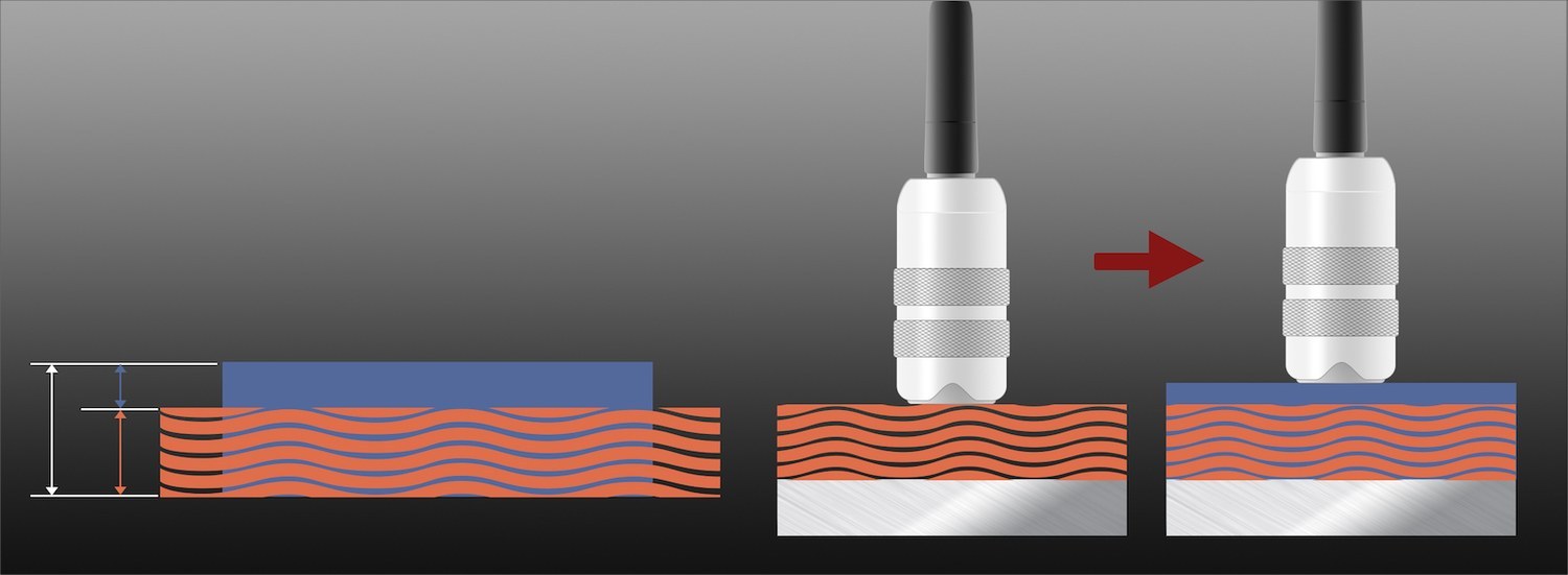
Measuring dry ink deposit thickness
The same reference-based approach can be used to measure dry ink deposit thickness. Place the unprinted substrate over the metal base plate and zero the probe using an average value. The substrate becomes the reference. Measurements taken on the printed substrate then indicate the thickness of the dry ink deposit rather than the total substrate thickness.
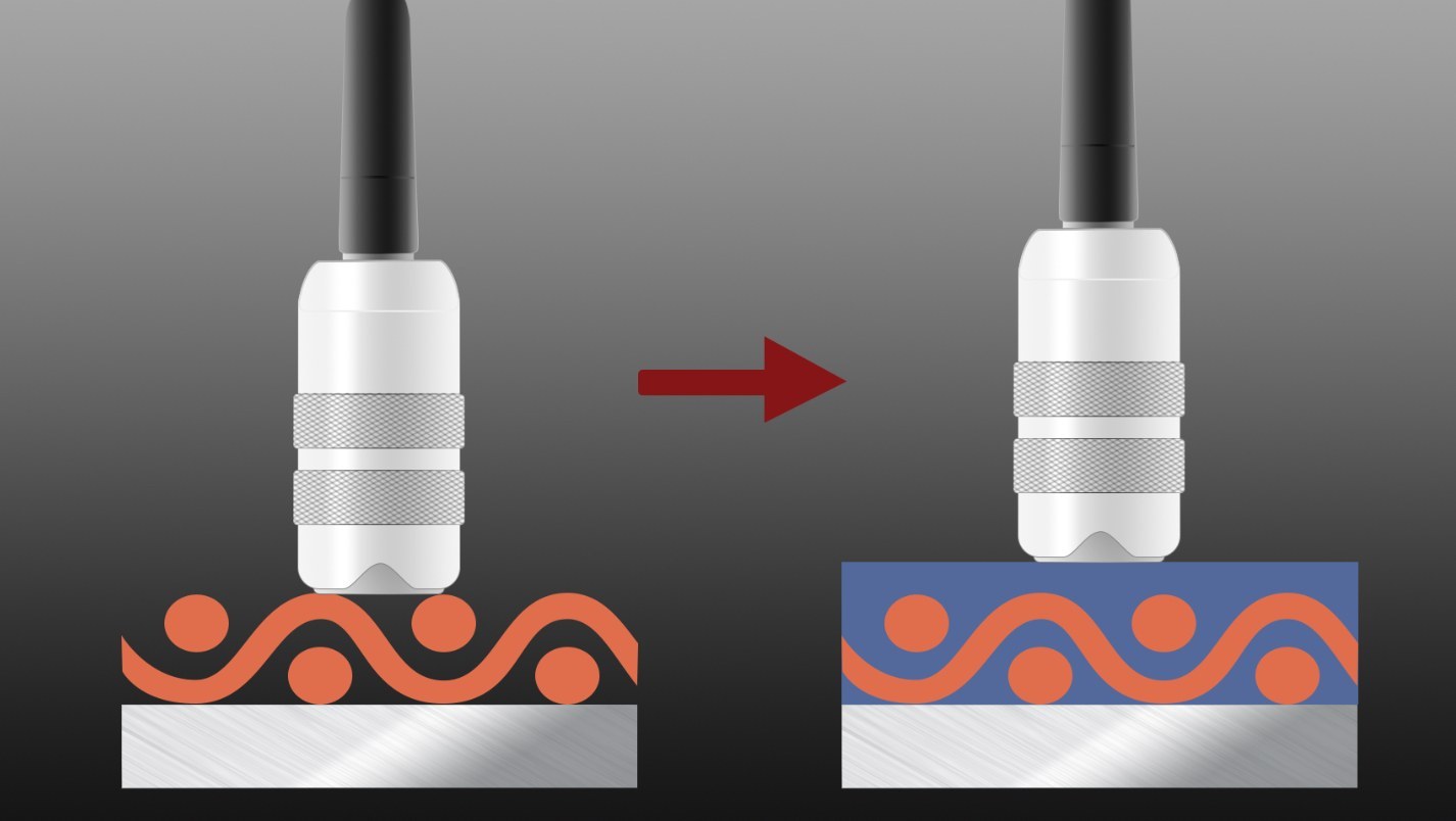
This method allows the coating thickness gauge to be used at multiple points on the printed surface without cutting samples to create an accessible measurement area, unlike certain mechanical measuring tools such as caliper or micrometer measurement approaches. Taking multiple readings remains useful where the substrate or printed surface is uneven.
A consistent thickness-control workflow
A practical workflow begins by measuring the tensioned mesh, then using that mesh as the baseline for stencil build-up checks. After printing and curing, zero on the bare substrate and inspect the dry ink deposit. Recording averages at consistent screen locations makes it easier to compare screens, coating conditions, and completed prints over time.
By monitoring the mesh, emulsion, total stencil thickness, and dry ink layer separately, operators can identify variations throughout the screen printing process. The coating thickness gauge uses a non-destructive measurement method to help monitor and control these thickness parameters.