Why measured amplitude can be lower than the real value
If an oscilloscope shows a lower amplitude than expected, the first thing to check is bandwidth. A simple test makes this clear: measuring a 100 MHz, 3.3V waveform with a 100 MHz oscilloscope may not produce an accurate amplitude reading. In this case, the limitation comes from the oscilloscope’s bandwidth, not necessarily from the signal itself.
What bandwidth means in an oscilloscope
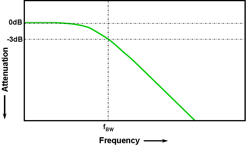
Bandwidth refers to the analogue bandwidth of the oscilloscope’s analogue front end. It directly affects how well the instrument can measure a signal. In practical terms, oscilloscope bandwidth is the highest frequency at which a sine wave can be measured without its amplitude falling below the -3 dB point, which is 70.7% of the true amplitude.
As signal frequency increases, the oscilloscope becomes less able to display the correct level. For a Gaussian-response oscilloscope amplifier, when the measured sine wave frequency equals the bandwidth, the measurement error is about 30%. That is why bandwidth should be chosen with margin, especially when measurement accuracy matters.
Why the 5x rule is commonly used
For accurate results, a common guideline is to choose an oscilloscope bandwidth that is about five times higher than the highest frequency in the signal being measured. This rule helps reduce amplitude error and gives the instrument enough room to reproduce the signal more faithfully.
For example, if a signal contains a highest frequency component that you want to measure accurately, the oscilloscope bandwidth should be much higher than that component. This is especially important because many real-world waveforms are more complex than pure sine waves and contain additional harmonic content.
How limited bandwidth distorts complex signals
Complex signals are made up of multiple harmonic sine waves. If the oscilloscope bandwidth is too low, some of those harmonic components are not effectively passed through the instrument. They may be blocked or attenuated, which can lead to amplitude distortion, loss of edges, and reduced detail.
As a result, features such as bells, tones, and other waveform characteristics may no longer have reliable measurement value. This is why bandwidth selection is not only about amplitude, but also about preserving the shape and detail of the signal.
Choosing bandwidth for different measurements
For high-frequency measurements, the full bandwidth should be used. The source text gives the example of measuring a 27 MHz crystal: if a bandwidth limit is enabled and set to 20 MHz, the waveform may become distorted and the measurement may lose value.
For low-frequency signals, bandwidth limiting can be useful. It acts as a high-frequency interference filter and can make the signal display more clearly. The key point is that bandwidth settings should match the measurement goal rather than being left at a fixed value for every task.
Bandwidth and rise time are closely related
Bandwidth is also tied to rise time. Rise time is usually defined as the time it takes for a signal to move from 10% to 90% of its steady value. In oscilloscope work, rise time helps describe how quickly the system can respond to a changing signal.
For oscilloscopes below 1 GHz, a common formula is RT = 0.35 / BW. Here, 0.35 is the scale factor between bandwidth and rise time in the first-order Gaussian model. This relationship allows you to estimate the minimum observable rise time from the specified bandwidth.
For example, if the oscilloscope bandwidth is 200 MHz, the minimum observable rise time is 1.75 ns. That means signals with faster edges than this may not be fully represented by the instrument.
Practical takeaway
If a measured amplitude is lower than the real value, the oscilloscope bandwidth is one of the first things to check. The wrong bandwidth can reduce amplitude accuracy, distort waveform details, and hide useful signal information. Matching bandwidth to the signal, applying the 5x rule when accuracy is important, and understanding rise time all help improve measurement reliability.
For electronics manufacturing and test workflows, these basics are essential for getting meaningful oscilloscope results and avoiding misleading readings.
Key points to remember
- Bandwidth directly affects amplitude accuracy on an oscilloscope.
- At the bandwidth limit, sine-wave measurement error can be significant.
- The 5x rule is a practical guideline for better accuracy.
- Low bandwidth can distort complex waveforms and reduce detail.
- Rise time can be estimated from bandwidth using RT = 0.35 / BW for oscilloscopes below 1 GHz.