6020 BMS ATE Application Note
A growing number of portable devices and vehicles rely on Li-ion or Li-Polymer batteries for their power. Examples thereof are mobile phones, laptops, cordless vacuum cleaners, drones and vehicles such as electric bicycles, scooters, cars, buses or boats. Charging these types of battery chemistries requires careful monitoring of voltage, current, temperature and state of charge (SoC). This is accomplished by integrating a battery management system (BMS) in the battery charger. These BMS equipped battery chargers must be thoroughly tested to ensure customer safety. Incidents of batteries catching fire are well documented and publicized and can do significant damage to companies that market such products. Prodigit developed the battery BMS test verification tool for this purpose. The BMS system provides a dedicated test and verification platform for testing of single cell batteries as well as multiple cells.
In battery-based system, major considerations include physical battery volume, operating temperature range, dust and waterproof resistance and environmental and safety parameters. The most important parameters are the performance of the battery system, including the battery capacity and energy, state of charge (SoC), voltage, Ampere Hour (AH) or Watt Hour (WH), internal resistance, energy efficiency, self-discharge and lifetime no of cycles. To ensure overall performance verification, it is necessary to test each single battery cell as well as the entire power battery system input / output (I / O).
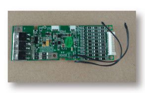
The selection of the BMS chip is mainly related to the number of battery and cells in series which determines the battery voltage. At the current state of the art, a single BMS devices analog front-end can monitor from 1 through 16 cells or 16 channels.
The main objectives of a BMS are focused on: low power consumption, high reliability and product safety. Most batteries used today are lithium batteries. Unfortunately, the safety record for lithium is not stellar. Because the characteristic of lithium is more dynamic, it is easier to cause an explosion or fire, but it has higher energy density that alternative chemistries. Thus, the battery module manufacturer has to include a BMS design with a high emphasis on protection features. From a single battery, battery pack and then to the entire BMS, each function has to include a protection mechanism to ensure safe and secure operation under all conditions. In addition, the BMS is also used to monitor for protection related criteria. This same monitoring function can also assist in prolonging battery life.
When the battery is charged and discharged, it is critical that the voltage balance between all cells is maintained to ensure that no individual cell overcharges or over-discharges.
The battery management system (BMS) is designed to protect the battery from damage, extend battery life and maintain battery performance. In other words, the battery management system plays an important role in achieving safety and performance requirements for rechargeable batteries.
1. The basic functions of the battery management system include:
- Measure the battery voltage
- Measure the battery input current (when charging) and the output current (when discharging)
- Measure the cell voltage.
- Measure the battery temperature (by NTC thermistor). The BMS needs to disconnect or limit the charge voltage or current with its protection delay. When there is an Over- Temperature or Under-Temperature condition, the BMS needs to reconnect the charge and/or discharge switch with a recovery time after the OTP or UTP condition is removed.
- When the above measured value exceeds the maximum or minimum limit, it needs to disconnect the battery, allow for a protection delay time, including over voltage (OV), under voltage (UV), over current (OCD), short circuit (SCD) etc. These steps also include protection recovery times for normal operation after protection is removed to meet design requirements.
- When there are multiple battery cells, it is necessary to balance the amount of battery stored in each battery pack.
- Check the operating status of the system components to ensure the safety of the battery management system.
- Status of Charge (SoC), Status of Health (SoH), and Status of Function (SoF) of the battery are calculated and tested.
- Calibration of the above measured values, programming the setting parameters, and feedback the information to the system through the communication interface of BMS.
Whether the battery management system can perform the above functions well depends on the accuracy of the input data of the battery sensor. This sensor directly affects the user's safety, so it needs to be testing 100% as part of BMS test verification. Because the BMS is a custom assembly product that is in connection with a dedicated battery, the test verification project is quite complicated and needs to be checked and confirmed step by step in order to ensure correct operation Therefore, an ATE test system is the best choice.
Since the battery BMS must be combined together with the battery and it is a highly customized device, the BMS parameters must be determined and set by the user. The ATE is just used to implement and confirm whether all condition meet the tools and platforms that can quickly and indeed do the verification. To avoid human error, the setting parameters for the BMS programming can only be applied to a specific lithium battery for use. It does not apply to other, different specifications of lithium batteries. Thus, the need for lithium batteries and BMS circuit board be combined together to perform the desired function and it is different from other standardized single-type components. In other words, the user does not have to worry about BMS parameter settings during ATE operation, but only confirm that the BMS protection & security functions are performed without error.
2. Test verification solution
For the lithium battery, charger and battery BMS, Prodigit provides the corresponding test solution respectively, Prodigit provides the industry's most wide range of models of electronic load product line, the power up to 60KW, the voltage up to 1000V, and the current up to 1000A, by the way, Prodigit also has provided a variety of customized specifications (by request) and BMS Short/OCP test option to meet the requirements of various tests on the market.
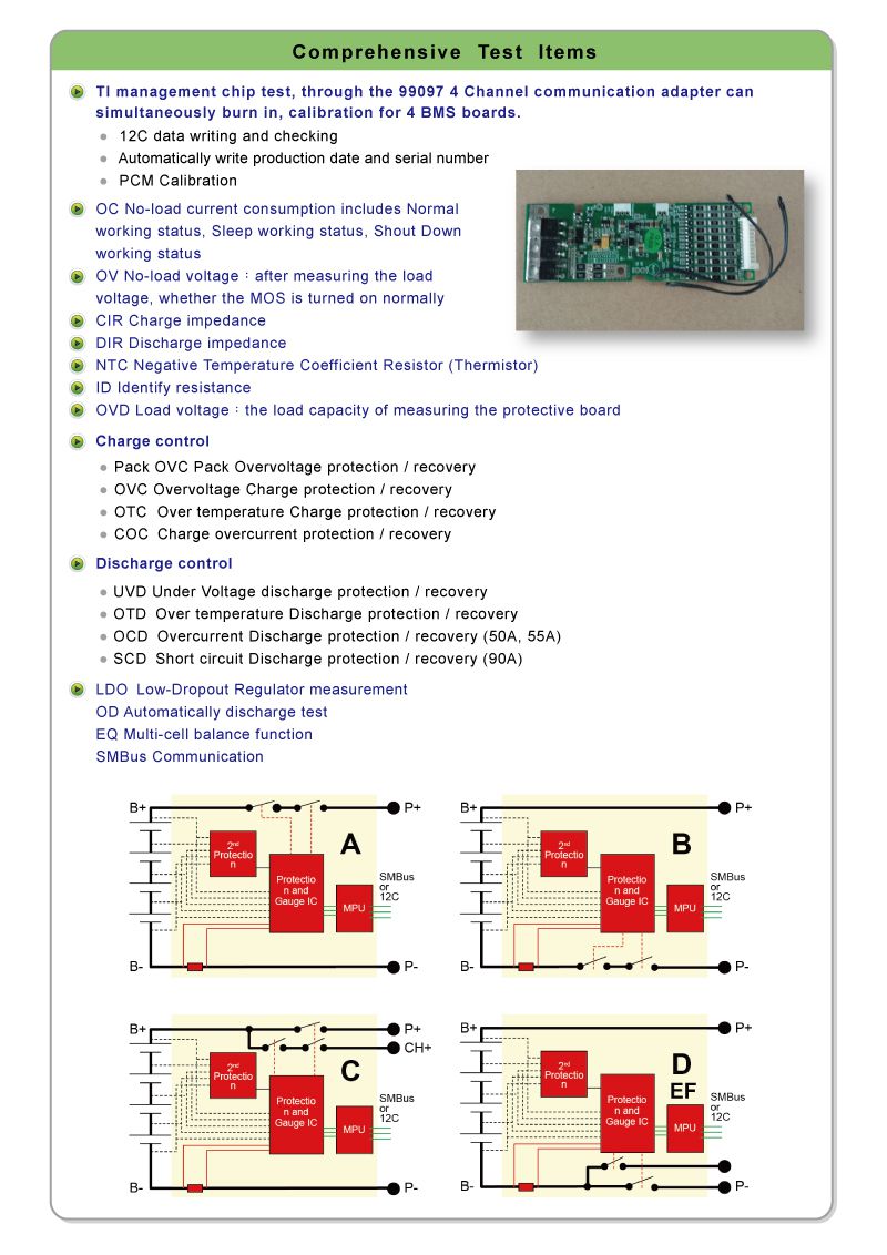
3. 6020 BMS ATE Test Function Items
Tl management chip test through the 99097 4 Channel communication adapter can simultaneously burn in, calibration for 4 BMS boards
- 12C data writing and checking
- Automatically write production date and serial number
- PCM Calibration
OC No-load current consumption includes Normal working status, Sleep working status, Shout Down working status
OV No-load voltage: after measuring the load voltage, whether the MOS is turned on normally
CIR Charge impedance
DIR Discharge impedance
NTC Negative Temperature Coefficient Resistor (Thermistor)
ID identify resistance
OVD Load voltage: the load capacity of measuring the protective board
Charge control:
- Pack OVC Pack Overvoltage protection/recovery
- OVC Overvoltage Charge protection / recovery
- OTC Over temperature Charge protection / recovery
- COC Charge overcurrent protection / recovery
Discharge control:
- UVD Under Voltage discharge protection / recovery
- OTD Over temperature Discharge protection / recovery
- OCD Overcurrent Discharge protection / recovery (50A. 55A)
- SCD Short circuit Discharge protection / recovery (90A)
LDO Low-Dropout Regulator measurement
OD Automatically discharge test
EQ Multi-cell balance function
SMBus Communication
5. Features:
- System Authority Assignment: User Authority Management, which allows different users to assign different permissions
- High Extensibility: for multi-string battery cell, 4 cells per channel, expandable from 1 to 16 cells per strings
- High compatibility: for a wide range of charge and discharge specifications, and with multi-level current protection test
- Battery simulation device modular design: Use one string 16 cells or four string 4 cells battery, simulation device can simulate 0.1 - 5V analog battery cell voltage, you can test the core specifications of the PCM product, such as: PCM OC sleep power self-consumption, each string CELL of the charge and discharge protection and balance function
- The communication method between the device and the system is RS-232 communication
- The Gauge IC communication protocol supports I2C, SMBUS and other customized communication protocol
- The Pass / Fail test result: the system can accurately measure the voltage and current changes. If the test result is NG, the system will automatically stop the test according to the protection setting conditions, and generate alarm function to remind the user
- Data processing and human-machine interface: Test data can be converted into EXCEL files. The selected conversion data items include data such as test items, Pass / Fail conditions, and test procedures, and support batch query and convert data
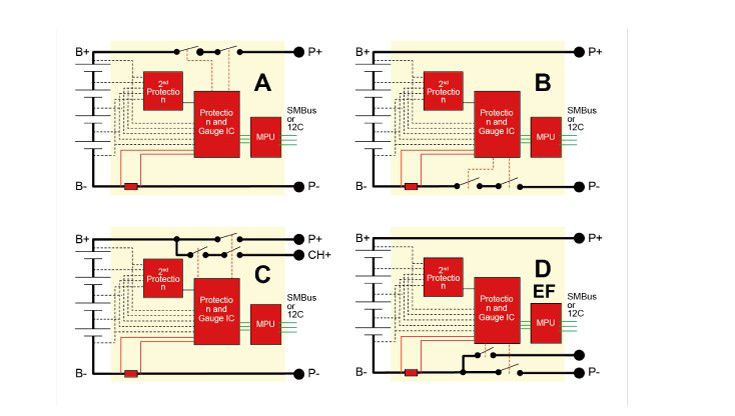
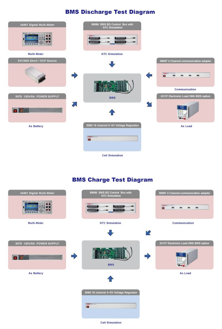
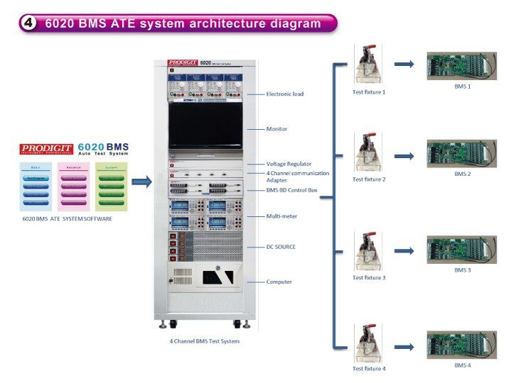
6. 6020 BMS ATE practical application
- PC with 6020 BMS Auto Test System installed and I/O control
- 3300F+3311F Electronic Load 60V/6GA/300W, Include BMS function, can sink the maximum load of 120A
- 5070 DC Power Supply 120V/25A
- 99096 BMS Switch Box
- 99097 4 channel communication adapter
- BMS Battery Simulator model 50SO Voltage Regulator can be configured as 1pc 16 strings or 4pcs 4 strings battery simulator
- 34461A Digit Multi-meter
- Short/ OCP Source 5V/10QA
- NTC Simulator
7. 6020 BMS ATE practical application
- Single Cell BMS
- Multiple Cell BMS
- R & D design verification test
- A large number of rapid testing in manufacturing
- Battery Pack/battery module verification and testing
For the BMS over current protection functions, including the battery overcharge, over discharge, short circuit etc. abnormal conditions, the Prodigit electronic load (Model 331OF) with BMS option is able to measure the BMS peak protection current and protection response time. If needed, Prodigit can provide the corresponding models to meet the market requirement for up to 100GA protection current.
For the BMS temperature detection, including over or under temperature protection action and after temperature recovery and protection. Prodigit designed an NTC module that can simulate the battery BMS NTC resistance values. Using the 3302F with NTC Option or the 6020 BMS ATE NTC simulation mode, the BMS temperature protection operation can be verified and the reaction of the delay and recovery time can be checked.
For the BMS DC internal resistance, AC internal resistance, BMS consumption current, battery cell balance, NTC simulation and a variety of other protections, the 6020 BMS high-performance automatic test system can provide simultaneous testing of 1 to 4 BMS. Each BMS function is tested step by step and quickly. The 6020 BMS test system can be configured as a single BMS test system for design verification or quality testing. It can also be configured as four BMS simultaneous testing systems for rapid testing in mass production environments.
For complete battery pack charge and discharge testing, Prodigit also provides the 9841 battery charge and discharge test system and software based on to the customer’s specific requirements. Test systems are designed to match the required power and electronic load to perform the battery charge and discharge related testing.
The 5020 BMS ATE can be purchased the whole system (Hardware + Software) or dedicated hardware in the system. Prodigit provides the operation and programming instructions for the dedicated equipment. This means the dedicated hardware such as the 5080 voltage regulator for battery cell simulation and the 99096 Switch Box with NIC simulation can be added to your existing ATE system. The user can also build his own custom ATE system.
6020 BMS ATE Ordering Information:
Please contact Prodigit sales office or distributor in your area.