Leaptronix LP-2600 逻辑线路实验板
制造商: LEAPTRONIX Model: LP-2600 来源: Taiwan - 联系
Manufacturer: Leaptronix
Model: LP-2600
Details
Smart Logic Design Experimental Kit
Introduction
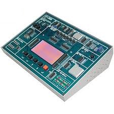
The LP-2600, a Smar t Logic Design Experimental Kit, which helps beginners to comprehend the general design functions of digital circuit, and offers multiple experimental units. The LP-2600 simplifies the process of welding ICs. As long as we load the entire circuit program into the Smart Logic Design Experimental Kit through printer port, the LP-2600 will simulate the circuit.
Features
- Do not require TTL and CMOS devices to do experimental circuits. Saving materials and time.
- Help users learn about practical experiments and basic logic programs quickly without soldering IC components.
- Offer smart INPUT and OUTPUT circuit linkage function.
- Offer practical input control settings. Reveal each gate, IC gate and output linkage results on output circuit.
- Offer the pin of measurement point for convenience to measure various test point virtually..
- Fit for standard digital logic experiment programs.
- System built-in various experimental units of basic logic gate, assembled logic and digital logic.
Experimental Content
- Basic Logic gates experiment
- Assembled logic gates experiment
- Adder experiment
- Subtracter experiment
- Assembled logic application
- Digital logic application
- Sequential logic experiment
- Sequential logic application
- D/A converter experiment
- A/D converter experiment
- 555 multi-vibrates circuit experiment
- PULL UP circuit experiment
Specification
- Power: 90V AC~260V AC
- Frequency Range: 50/60 Hz
- Dimension: 32cm x 22.6cm x 3.0/8.5cm
- Weight: 2.8Kg
- Operating Altitude: up to 5000 m
- Operating Humidity: 90% (non-condensing)
- Temperature: +5℃ ~ +45℃
Other Specifications
Devices Emulating Module
- Display:240x128 LCD
- Emulating:
1. TTL IN (x28) Pin
2. TTL OUT (x28) Pin
3. O.C. OUT (x6) Pin - Control keypad:FUNC, ESC, UP, DOWN, ENTER
Input Unit
Logic Switch:S1~S8
Signal Generator:
- A, /A →100 ms Pulse
- B, /B →100 ms Pulse
- Clock:1 Hz/10 Hz/100 Hz/1 KHz/10 KHz/100 KHz/1MHz
- CLK/2, CLK/4, CLK/8, CLK/16, CLK/32, CLK/64, CLKIN
Output Unit
Standard Circuit Module:
- Common anode LED display x 8
- Common cathode LED display x 8
- Isolated common anode 7 segment display x 2
- 8 x 8 monochrome dot matrix LED
- BUZZER unit 6. VH, VL, common point x 4
Advanced Circuit Module:
- 555 Circuit unit (a. Mono-stable oscillator / b. Non-stable oscillator)
- D/A unit 4bit
- A/D unit 7bit
- PULL UP circuit experiment
Advanced Software Module::
Allow users to edit and revise experimental circuits.
- To download experimental circuits to experimental lab
- To create experimental circuits for various certificated levels
- 质量承诺
- 正品保修
- 送货到家
- 交易简单化