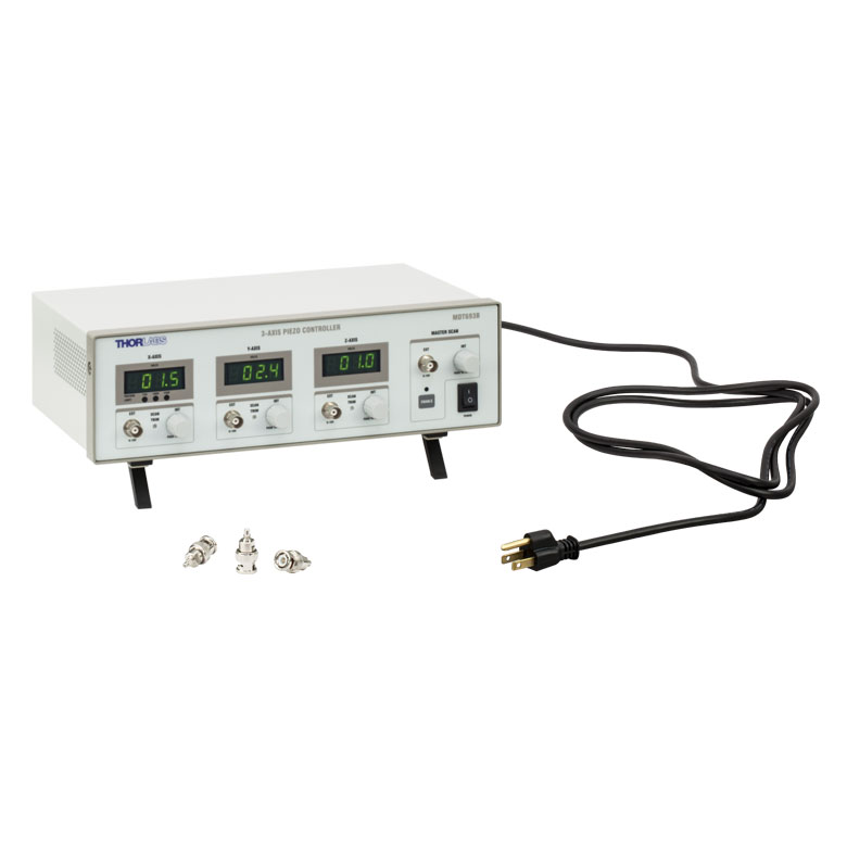
THORLABS MDT693B 开环压电控制器 (3-Channel)
制造商: THORLABS Model: MDT693B - 联系
Number of Channels: 3
Connectors: BNC (One BNC-to-SMC Adapter per Channel Included)
Output Voltage: 0 - 75 V, 0 - 100 V, or 0 - 150 V (Selected by Switch on Rear)
Output Voltage Resolution
When Using Knobs:
- 1.1 mV (for 75 V Output Voltage Setting)
- 1.5 mV (for 100 V Output Voltage Setting)
- 2.2 mV (for 150 V Output Voltage Setting)
Output Current (Max): 60 mA
Output Noise(a): 1.5 mV (RMS) ~9.9 mV (Peak-to-Peak)
Output Impedance (Max): 150 Ω, 1.0 nF
Load Impedance(b) (Min): 2.5 kΩ
Bandwidth(-3 dB):
- 9 kHz (No Load, Small Signal)
- 8.5 kHz (No Load, 150 Vpp)(c)
- 200 Hz (1.4 µF Piezo, 150 Vpp)(c)
Bandwidth Stability (-3 dB): <0.01% Over 5 Hours
External Control through BNC
Input Voltage: 0 - 10 V
Input Impedance: 10 kΩ
Input Gain:
- 7.5 V/V ± 5% (for 75 V Output Voltage Setting)
- 10 V/V ± 5% (for 100 V Output Voltage Setting)
- 15 V/V ± 5% (for 150 V Output Voltage Setting)
Output Voltage Resolution When Using BNC: Limited by Noise of External Voltage Source
Scan Trim Gain Adjustment: 80% to 120% of Sum of Master Scan External Voltage and Offset from Rotary Adjustment Knob
External Control through Command Line
Physical Interface: Female Type B USB 2.0 Connector
Digital-to-Analog Resolution: 16-Bit, 2.75 mV
Analog-to-Digital Resolution: 16-Bit, 3.0 mV
Physical Specifications
Display Type: 7-Segment LED with Four Digits
Display Resolution: 0.1 V
Enclosure Size: 12.18" × 4.15" × 8.55" (309.4 mm × 105.5 mm × 217.1 mm)
Weight: 3.02 kg (6.65 lbs)
Operating Temperature: 10 to 40 °C
Power Specifications
Input Voltage: 100 - 240 VAC
Input Frequency: 50 - 60 Hz
Input Power (Max): 60 VA
Fuse Type: IEC6012
Fuse Dimensions: 5 mm x 20 mm
Fuse Rating: 600 mA
(a) Tested without an external load connected (1 nF output impedance only). Adding a capacitive load, such as a piezo, will decrease the noise because the capacitance will create a low-pass filter with the output resistance.
(b) The smallest allowable terminating resistance. Applying lower impedances will cause the short-circuit protection to limit the output voltage. Continued use in this mode will cause circuit degradation and eventual circuit failure.
(c) Assume a ramp function is used. The bandwidth depends upon the load and requires a calculation for a more representative number. See Chapter 6 of the manual for details.
- 质量承诺
- 正品保修
- 送货到家
- 交易简单化