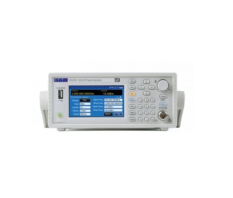
TTI TGR2051 射频信号发生器 (150kHz - 1500 MHz)
制造商: TTI Model: TGR2051 来源: United Kingdom 保障: 12 Month - 联系
FREQUENCY
Frequency Range: 150kHz – 1500MHz
Setng Resolution: 10Hz
Setng Resolution Low Spur mode: 1MHz
Accuracy/stability: see Reference Frequency
Phase Noise: 500MHz Carrier: <-124dBc/Hz (typ) @ 10KHz offset
1GHz Carrier: <-117dBc/Hz (typ) @ 10kHz offset
See chart below
Residual FM: <2 Hz @ 1GHz - Equivalent peak deviation in a 300Hz to 3.4kHz
bandwidth.
Internal Reference Accuracy: <± 1ppm, 15ºC – 30ºC
<± 2ppm, 5ºC – 40ºC
Internal Reference Stability: <1ppm/year
Reference IN & OUT: Both can be disabled when not required.
Reference IN
Rear Panel BNC:
10MHz +/- 25ppm, 50Ω input impedance, 2 - 5Vpp
Automatc detection and selection when an external reference signal is
present and Ref. Clock is selected to be EXTERNAL.
LCD status indicator shows when external reference is actve.
Reference OUT
Rear panel BNC:
10MHz, 50Ω output impedance, >2Vpp into 50Ω
The actve reference signal (from internal or external source) is present
when Ref. Clock Out is selected to be ON.
OUTPUT LEVEL
Output Level Range: –127dBm to +13dBm
Setng Resolution: 0.1dB, 0.01uV –1mV
Accuracy: ±1dB output levels > -53dBm
±2dB output levels <= -53dBm
Additonal Uncertainty
AM, ASK & OOK ON:
+/-0.5dB
Harmonically Related Signals: <-25dBc @ +13dBm, <-30dBc@levels <=0dBm
Non-harmonic Spurii: <–50dBc >10kHz offset 1.5GHz – 3GHz
<-56dBc > 10kHz offset 150KHz - 1.5GHz
Output Impedance: 50Ω
VSWR: <2.0 typ <=1.6
RF Output Connector: Type N Female
Reverse Voltage Protection: 50V DC
Output Switch: RF OUT On/Off switch with LED showing ON status
ANALOG MODULATION
SOURCE
Internal: DDS generator providing
sine, square, + Ramp, - Ramp, triangle
1mHz – 1MHz, Resolution 1mHz
Signal available at MOD IN/OUT, 150Ω source impedance
External: 100Hz – 1MHz, 1dB relative to 1kHz, 1Vp-p for full scale
10kΩ input impedance AC coupled
FREQUENCY MODULATION
Deviation: 1mHz – 1MHz subject to carrier frequency
Deviation Setng Resolution: 1mHz
Deviation Accuracy: Ref freq accuracy +/- 1mHz for internal modulation
±2% for external modulation @ 1kHz, 1V p-p
Distortion: <1% @ 1kHz modulation, 300 – 3.4kHz bandwidth.
PHASE MODULATION
Deviation: 0 - 25.00 rad
Deviation Setng Resoluton: 0.01 rad
Deviation Accuracy: Ref freq accuracy ±0.1rad for internal modulation
±2% for external modulaton @ 1kHz, 1V p-p
Distortion: <1% @ 1kHz modulation, 300 – 3.4kHz bandwidth
AMPLITUDE MODULATION (LEVELS ≤+7DBM)
Modulaton Depth: 0 – 100%
Setng Resoluton: 0.1%
Accuracy: ±1% for internal modulation
±2% for external modulation @ 1kHz, 1V p-p
Distortion: ≤1% @ ≤90% depth10
DIGITAL MODULATION **
SOURCE
Internal: NRZ Paterns: Square Wave, User Defned Patern, 7-bit PRBS,
9-bit PRBS, 11-bit PRBS, 15-bit PRBS.
User Defined Patern: 16384 states can be created in the instrument or
downloaded via the remote interfaces.
Bit rate: 1mbits/sec – 1Mbits/sec
Modulation signal available at MOD IN/OUT, 150 Ω source impedance
External: Input via
MOD IN/OUT:
DC – 1Mbits/sec, >=2Vp-p, logic threshold +1.5V nominal.
10kΩ input impedance
INTERNAL MODULATION PATTERN TRIGGER
Source: External +ve edge, External –ve edge, Manual, via remote interface or Internal.
Internal trigger repeats at a programmable rate of 1 per 1us – 999.999999s
Modes: Immediate: Modulation starts immediately.
Triggered: Modulation waits for a trigger event.
Trigger Types: Infinite: First trigger event starts the modulation patern,
which repeats indefnitely.
Finite: Each trigger event starts one modulation patern (one
‘block’) or a count of bits in the modulation patern.
The bit count is programmable and can be greater
than a patern length.
Bit count range: 1 – 2^31
Trigger Delay: <500ns from specifed edge of external trigger signal to modulation start.
INTERNAL MODULATION PATTERN SYNC
Signal available from the rear panel SYNC BNC to synchronise internally produced modulation paterns.
SYNC modes: OFF, Start, Bit Rate, Bit Rate/2
SYNC polarity: High going SYNC pulse
Start SYNC: SYNC pulse 1 bit period wide at the start of the modulation patern.
Bit Rate SYNC: ½-bit period wide pulses at the modulation bit rate repeated indefinitely or for a
programmed repeat count from the start of the modulation patern in triggered
mode.
Bit Rate/2 SYNC: As for Bit Rate SYNC but at half the modulation bit rate.
FREQUENCY SHIFT KEYING
Modes: FSK, GFSK, MSK, GMSK, HMSK, 3FSK, 4FSK
Continuous phase frequency modulation.
Filter Settings: None, Gaussian (BT=0.3, 0.5 or 0.7), Raised Cosine (α =0.5 or 0.7), Root Raised
Cosine (α =0.5 or 0.7), Half sine.
Deviation: 1mHz – 1MHz subject to carrier frequency
Deviation Setng Resolution: 1mHz
Deviaton Accuracy: Ref freq accuracy ±1mHz for internal and external modulation
4FSK Encoding: Gray Code or Binary.
Encoding Synchronisaton
Internal Modulaton Source:
3FSK Start SYNC output indicates the start of encoding
4FSK Bit Rate/2 SYNC output indicates the start of encoding
Encoding Synchronisaton
External Modulation Source:
3FSK
4FSK
The external Trigger input can be used to defne the start of encoding
for both.
PHASE SHIFT KEYING
Modes: PSK
Deviation: 0 - 25.00 rad
Deviation Setng Resolution: 0.01 rad
Deviaton Accuracy: Ref freq accuracy ±0.1 rad for internal and external modulation
AMPLITUDE SHIFT KEYING (ASK)
ASK Depth: 0 - 100%
Setng Resolution: 0.1%
Accuracy: ±1% for internal and external modulation
Internal Rate: 1mb/s - 1Mb/s
External Rate: DC – 1Mb/s
ON-OFF KEYING (OOK) (BASIC PULSE MODULATION)
On-Off Rato: >80dB
External Input: Logic high = Carrier On
Internal Rate: 1mB/s - 1Mb/s
External Rate: DC – 1Mb/s
Rise/Fall Time: 50ns
FREQUENCY and AMPLITUDE SWEEP
Frequency setling tme to within 100Hz or 0.1ppm of
fnal frequency if greater:
<5ms*, typ <2ms
Amplitude setling tme to within 0.2dB: <5ms*, typ <4ms
Rear panel SYNC pulse width (defnes guaranteed
setling period):
5ms *
*Setling time and SYNC pulse width is extended to 15ms for all points in the sweep if the frequency crosses
250.00000MHz between any points in the sweep.
STEP SWEEP
Step frequency and/or amplitude according to a formula over a specifed number of points.
Number of Points: 2 - 1000
Formula specifes: Sweep Start and Stop Frequencies
Sweep Start and Stop Amplitudes
Dwell tme following SYNC at each point
Dwell Time: 0.01 – 10.000sec
Sweep Mode: Continuous or Single
Sweep Direction: Up or Down
Sweep Point Spacing: Linear or Logarithmic
Sweep Trigger : (Sweep start
held untl trigger event)
Manual, ext signal +ve or –ve edge, tmed (0.01 – 999.9sec) or via remote
interface
Point Trigger : (Sweep point
stepping held until trigger event)
Manual, ext signal +ve or –ve edge, or via remote interface
Point Trigger tming: >=10ms afer SYNC signal
SYNC signal (‘output stable’): Available afer output has setled at each point until next point.
Programmable high or low logic.
GENERAL
Power: 85…264Vac, 47…63Hz, 35VA max. Installaton Category II.
Standby <0.5W
Display: 4.3 inch (10.9 cm) backlit TFT LCD, 480 x 272 pixels total, 16 colours, resistive touch
screen.
Data Entry: Multple entry methods; keyboard or touch screen selecton of all major functons; edit
feld selecton by screen touch or rotary control; value entry by keyboard, rotary control
or touch screen; frequency and amplitude adjustable by value entry, character scrolling,
user defined step values or a combination.
Storage: 4G bytes internal storage available for 1000’s of instrument setups, sweep lists and user
defined modulation paterns.
Operating Range: +5°C to +40°C, 20 - 80% RH
Storage Range: –20°C to + 60°C
Environmental: Indoor use at alttudes up to 2000m, Pollution Degree 2.
EMC: Complies with EN61326
Safety: Complies with EN61010-1
Size: 2U high, half rack width.
Weight: 3 kg
Options: 19-inch rack mountng kit.
- 质量承诺
- 正品保修
- 送货到家
- 交易简单化