Testing Solar PV Strings for Zero Current Before Maintenance Using F404T Clamp Meter
In a solar power plant, the most dangerous moment is not when the system runs at full capacity. It happens right before a technician disconnects connectors, replaces fuses, or opens inverter enclosures... after isolating the PV string.
Why is PV string maintenance much more dangerous than most people think?
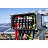
Solar panels are connected in series to form strings to increase voltage, strings are connected in parallel to increase current, and then inverters convert direct current (DC) into alternating current (AC). On modern high-voltage architectural systems, solar strings operate at DC voltages up to 1,500 V DC.
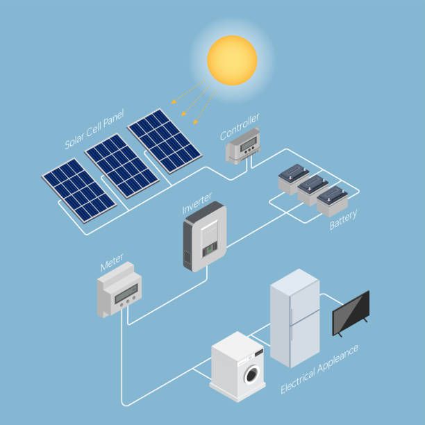
When exposed to sunlight, panels generate power, making string isolation fundamentally different from cutting a circuit that can be powered off at the source.
Risk: Direct Current Arc Flash (DC Arc Flash)
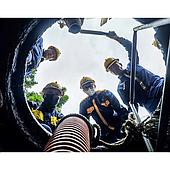
Every time technicians replace panels, connectors, DC fuses, or inspect inverter inputs, they must isolate a part of the system from the grid. DC current lacks a natural "zero-crossing point" like AC current, making an electric arc generated when disconnecting a live connector extremely difficult to self-extinguish. A DC arc flash is a real fire and injury hazard, not just a theoretical risk.

Does a clamp meter reading 0 A guarantee that the PV string is dead?
Official patent documentation from Chauvin Arnoux clearly explains why: Clamp meter measurements can be unreliable if the instrument is damaged, suffers component failure, has drifted out of calibration after extended field use, or if the technician configures it incorrectly (e.g., set to AC current mode when measuring DC current).
Risks from Hidden Equipment Faults
When a clamp meter's measuring circuit fails, the display may still show 0 A. Technicians trusting this zero reading will proceed to disconnect connectors, instantly triggering a dangerous electric arc.
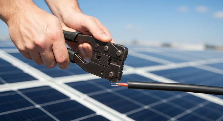
International Safety Principles
Test instruments must undergo operational verification (Self-Test) prior to being used to verify a de-energized circuit. For DC currents, the challenge is that standard reference current sources are rarely available in the field.

Patented Solution: Proprietary Autocheck on Chauvin Arnoux F404T
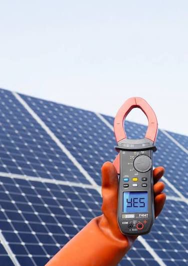
The Chauvin Arnoux F404T clamp meter directly solves this critical gap with its patented Autocheck function. With a single keypress, the device generates an internal DC current to verify whether the clamp reads the value correctly. Technicians only confirm the PV string is de-energized after the self-test passes (showing YES on display).
Optimal Technical Specification Comparison for Solar PV
| Measurement Parameter | F404T Range | Significance in Solar PV Maintenance |
|---|---|---|
| DC Voltage | Up to 1,700 V DC | Provides safety margin for 1500V strings when ambient temperature drops, increasing open-circuit voltage (Voc). |
| DC / AC Current | 1,500 A DC / 1,000 A AC | Measures string operating currents, detects string imbalances, and inspects central inverter inputs. |
| Electrical Safety Category | CAT IV 1000V / CAT III 1500V | Withstands transient overvoltages in large-scale utility solar industrial environments. |
| Enclosure Rating | IP54 | Dust and splash-resistant, featuring single-touch button design for easy operation with protective gloves. |
5-Step Procedure for Absolute Safety Verification
Disconnect the circuit following the plant's lockout/tagout (LOTO) safety procedure.
Verify that the F404T clamp measuring circuit works properly and is set to DC mode.
Clamp the 48mm jaw around the cable, read the current value, and confirm zero current flow (0 A).
Perform voltage testing on the operation points (zero current does not mean zero voltage).
Safely disconnect MC4 connectors, replace fuses, or perform inverter maintenance.
Learn More About Chauvin Arnoux F404T Solar PV Clamp Meter
Product imported and officially distributed by EMIN Group.