Why Do PCB Damages Concentrate During Transfers Between Stages?
Inside a machine, the PCB is clamped, positioned, and moved by mechanisms engineered specifically for it. Between machines, however, the board relies on human hands, magazines, guide rails, conveyor belts, and the cycle timing of two adjacent units. Every handoff point is a potential spot for misalignment, hesitation, or impact. Even on a line with high-precision equipment, mechanical defect rates remain elevated if inter-machine transfers are not properly engineered.
How to Read Damage Marks to Pinpoint the Root Cause
Instead of guessing broadly, inspect the physical shape of the damage to isolate the exact point of failure:
A straightforward yet effective practice is performing quick visual checks at the entry and exit of each stage while logging board barcodes to trace which stations damaged PCBs passed through. After a few days, you will have a clear defect map identifying your highest-risk transfer points, making subsequent investments data-driven rather than guesswork.
Where Does Manual Handling Damage PCBs, and How Do You Standardize It?
- Gripping boards across populated component zones instead of the edges, smearing solder paste, shifting parts, or leaving skin oils.
- Stacking PCBs directly on top of one another while waiting, causing the component side of one board to scrape the underside of another.
- Inserting boards at an angle into storage racks, leading to jamming or harsh friction when pulling them out or pushing them in.
- Deploy ESD-safe PCB magazines with fixed slotted dividers so each board rests in its own dedicated slot without touching adjacent boards.
- Enforce strict edge-only handling rules paired with ESD gloves or finger cots across all stations.
- Strictly prohibit direct board stacking at every buffer point. While low-cost and fast to deploy, procedural discipline only reduces human error—it cannot eliminate manual handling risks altogether.
How Do Machine Cycle Mismatches and Rail Misalignments Cause Board Drops?
When an upstream machine discharges a PCB before the downstream unit is ready, boards pile up at the junction—colliding, jamming, or riding up over one another. Because individual machine cycle times rarely match perfectly, bottlenecks frequently occur whenever a downstream station pauses for feeder replenishment, error recovery, or inspection.
Alongside timing signals, mechanical rail and conveyor misalignments trigger two common failures: incorrect rail width (too tight causes friction and jams; too loose lets boards tilt and drop off the track) and worn belts or height offsets between adjacent conveyors that create a step, causing boards to snag or jolt at the seam. Regularly inspect rail width after every product changeover, conveyor pass height relative to neighboring machines, and belt tension. Sliding a test board across the junction by hand to feel for resistance often exposes mechanical issues faster than spec sheets.
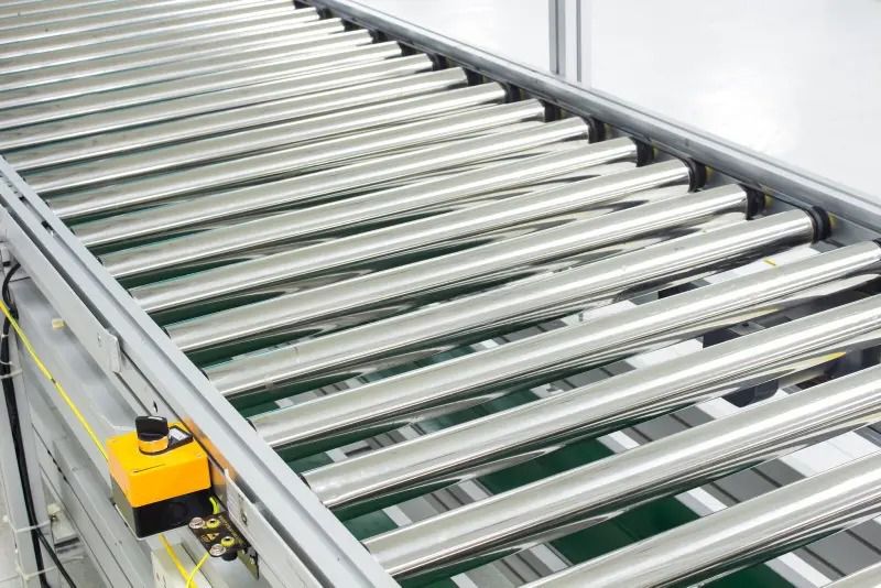
Automated PCB Handling & Conveyor Solutions at EMIN
To eliminate bottlenecks from manual handling, double-sided board flipping, and complex factory floor layouts, equip your SMT line with dedicated PCB handling modules:
Clamps the PCB securely by its edges and rotates it smoothly at controlled speed, completely eliminating hand contact, smeared solder paste, or drops on double-sided assemblies.
Automatically indexes magazines and feeds individual PCBs into the line in sync with SMEMA signals, removing manual loading where entry-stage damage concentrates.
Receives finished boards off the conveyor and slots them neatly into individual magazine grooves, safeguarding high-value assemblies at the end of the SMT line.
Versatile modules: single-rail Censtar BC-100XL-N, turn conveyor Censtar CN-XL-N, auto barcode scanner I.C.T BCS-M, and shuttle conveyor Suneast MC-250.
Key Specs to Verify and a Practical Upgrade Roadmap for Your Line
Before finalizing any PCB conveyor configuration, verify five core technical parameters to ensure seamless integration with your existing line:
An effective upgrade roadmap starts by measuring and logging where defects occur: if damage clusters at line entry and exit, prioritize loaders and unloaders; if defects happen at inter-machine junctions, synchronize SMEMA signals, align rail heights, and add buffer conveyors; if double-sided boards suffer the most damage, an automated board inverter comes first. Alongside hardware upgrades, maintaining standardized manual procedures and ESD magazines remains essential.
Every damaged PCB carries the material, placement, and rework costs of every preceding process. Reducing mechanical handling defects between stages is therefore one of the highest-ROI improvements you can make on an SMT line.
Contact EMIN's engineering team with your PCB dimensions, pass height, and defect hotspots to get matched with the right Anda, Manncorp, Censtar, I.C.T, or Suneast solution and a detailed quote.