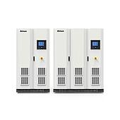
For meaningful PV inverter testing, a programmable DC power supply with solar simulation capability is generally more suitable than a basic constant-voltage or constant-current laboratory supply. The source must match the inverter’s DC limits while reproducing the solar array I-V behavior used by MPPT control.
Start with the inverter’s maximum DC voltage, MPP voltage range, maximum input current, short-circuit current, and maximum input power. Then determine whether the test needs dynamic solar simulation, high-speed measurement, automated test sequences, or energy sinking.
Summary: Use a solar array simulator (SAS) to emulate a PV array I-V curve. Size voltage above maximum open-circuit voltage, and size current and power above inverter demand. Assess dynamic response, measurement and logging capability, and regenerative sinking for shutdown-related tests.
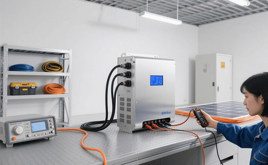
Why is a standard DC power supply often insufficient for PV inverter testing?
A standard DC supply provides constant voltage or constant current, whereas a PV inverter operates against a non-linear and variable solar-array current-voltage curve. It may therefore power an inverter at a fixed condition but cannot necessarily reproduce the behavior needed to assess MPPT performance.
A solar array simulator (SAS) is a programmable DC power supply with solar simulation mode. It can represent the I-V curve of a panel or array, including key operating points and changing environmental conditions.
| Source type | Output behavior described in the source | Typical testing implication |
|---|---|---|
| Standard DC power supply | Constant-voltage or constant-current output with low output impedance | May support a basic fixed-voltage functional check |
| Solar array simulator | Programmable solar I-V curve and higher-impedance panel-like behavior | Supports MPPT and changing-condition simulation |
How should voltage, current, and power ratings be selected?
Select a source whose voltage range exceeds both the inverter’s MPP voltage range and its maximum open-circuit voltage (Voc). The source material suggests allowing a 20% voltage margin above maximum Voc.
Its current rating should exceed the inverter’s maximum input current and short-circuit current (Isc). Total source power must also cover the inverter’s maximum DC input power, with the source suggesting a 20–25% power margin for selection.
| Parameter to review | Selection basis | Example from the source |
|---|---|---|
| Voltage | MPP range and maximum Voc, with margin | 950 V Voc × 1.2 = at least 1140 V |
| Current | Maximum input current and Isc, with margin | 15 A input current may call for 20 A or 30 A |
| Power | Voltage × current, covering maximum inverter input power | 1000 V × 30 A = 30 kW |
Note: A margin is a sizing practice, not a substitute for checking the inverter’s actual input specifications and the test setup’s operating conditions.
Which solar simulation features matter for MPPT testing?
The SAS should allow programming of the full I-V curve using open-circuit voltage (Voc), short-circuit current (Isc), and voltage and current at the maximum power point (Vmp and Imp). A stable, repeatable curve with a distinct knee gives the inverter’s MPPT algorithm a defined operating characteristic to track.
Dynamic simulation is also useful when the test must represent changing irradiance or temperature. The source describes varying Isc to represent irradiance changes and varying Voc to represent temperature changes.
Why do measurement accuracy and logging speed matter?
Voltage and current measurements determine the calculated DC input power used in inverter efficiency evaluation. The source identifies high measurement accuracy, such as 0.1% or better, as important when calculating efficiency from AC output power divided by DC input power.
High-speed logging of voltage, current, and power helps capture transient events and MPPT hunting behavior. Review whether the available logging rate, data handling, and reporting functions fit the intended validation procedure.
When is regenerative sinking capability important?
A regenerative SAS can both source power and sink current, allowing it to absorb energy returned from the inverter side. This is particularly relevant when an inverter stops drawing input power while its DC-link capacitors remain charged, such as during an anti-islanding or grid-loss protection test.
Without sinking capability, the source describes a risk of output-voltage overshoot when returned energy cannot be absorbed. For safety-function, validation, or compliance-oriented work, regenerative behavior should therefore be assessed explicitly against the test requirement.
What controls and integration options should be checked before purchase?
Front-panel controls support basic setup and quick checks, while PC software supports automated sequences, data logging, report generation, and I-V curve plots. Confirm that the software and available interfaces fit the existing test rack and automation environment.
The source lists Ethernet, GPIB, and USB as interfaces to verify, and notes that automation environments may require compatible drivers such as IVI, LabVIEW, or DLL support. These integration details can determine whether a properly sized source is practical in the intended workflow.
Can a programmable DC source be used for a basic production test?
A high-power programmable DC source may be sufficient for a basic go/no-go check in which the goal is only to verify that an inverter starts and produces AC power at a fixed input voltage. That approach does not establish MPPT behavior or meaningful performance under a solar-array I-V curve.
For R&D, performance validation, and tests that require solar-array behavior, prioritize an SAS with solar simulation mode, suitable transient response, measurement capability, and regenerative sinking when the procedure calls for it.