Photovoltaic inverter testing evaluates how an inverter converts power, tracks available solar power, responds to grid events, and operates under defined environmental conditions. A useful test program combines electrical measurements with controlled simulations of changing irradiance, load, grid, and fault conditions.
For photovoltaic energy-storage systems, the inverter handles bidirectional DC/AC conversion and power management between photovoltaic generation, batteries, loads, and the grid. Testing therefore needs to cover both normal operating performance and protective responses.
Summary: Test conversion efficiency at multiple loads; verify MPPT behavior during changing irradiance; simulate grid and DC-side faults; and record power quality, environmental operation, and protection responses.
What should photovoltaic inverter testing measure first?
The first measurements should establish input and output electrical behavior: DC-to-AC conversion efficiency, output voltage, frequency, waveform, and harmonic content. Measurements at more than one load point, such as 25%, 50%, and 100%, help show how performance changes across the operating range.
Low-load operation also deserves separate attention because it can reveal standby or light-load energy use. For long-duration operation, recorded data can be reviewed for unusual fluctuations and component temperature rise.
| Test area | What is evaluated | Typical test condition from the source |
|---|---|---|
| Conversion efficiency | DC-to-AC power conversion | 25%, 50%, and 100% load points |
| Dynamic response | Response to changing solar input | Irradiance change from 1000 W/m² to 500 W/m² |
| Power quality | Voltage, frequency, waveform, and harmonics | Output measurement during operation |
How is MPPT performance tested on a photovoltaic inverter?
MPPT testing uses a programmable DC power source to reproduce changes in the photovoltaic array I-V curve. The purpose is to observe whether the inverter can identify and follow the maximum power point as irradiance changes abruptly or temperature varies.
A changing irradiance profile is particularly useful because the inverter must react to a moving operating point rather than a fixed DC input. The test should capture response speed and tracking behavior alongside power measurements.
Which protection functions should a photovoltaic inverter test include?
Protection testing should simulate grid abnormalities and DC-side fault conditions, then confirm the inverter response and alarm behavior. Relevant grid events include overvoltage, undervoltage, overfrequency, and underfrequency; DC-side checks include reverse connection, overvoltage, and insulation faults.
Islanding protection is also tested by reproducing a grid-loss condition, commonly with an adjustable RLC resonant load. In the source example, the RLC load is matched to inverter rated power, the quality factor is set to Qf=1.0±0.05, and grid disconnection is initiated through switch K1.
Note: The source describes observing whether grid connection is interrupted within 0.2 seconds in its islanding example. Applicable settings and acceptance criteria should be defined for the inverter and test context.
How do grid adaptability and EMC tests assess inverter behavior?
Grid adaptability testing examines how the inverter behaves during voltage changes and whether its output current contains harmonics that meet the applicable requirements. LVRT and HVRT simulations reproduce temporary voltage dips or surges to assess the ability to remain connected during grid disturbances.
EMC testing includes conducted and radiated interference checks. The source identifies IEC 61000-3-2 for harmonic-related evaluation and EN 55032 for EMC-related evaluation; the applicable standard and test configuration should be selected for the specific product and market.
What environmental conditions can be used to test photovoltaic inverter stability?
Environmental adaptability can be assessed by operating the inverter at high temperature, low temperature, and hot-humid conditions. The source gives examples of +50°C and -25°C operating tests to check stability across temperature extremes.
During these tests, acquisition equipment can record parameters such as temperature and voltage in real time. Comparing these records with electrical performance measurements helps identify changes that may not be visible in a short functional check.
What equipment is used in a photovoltaic inverter test system?
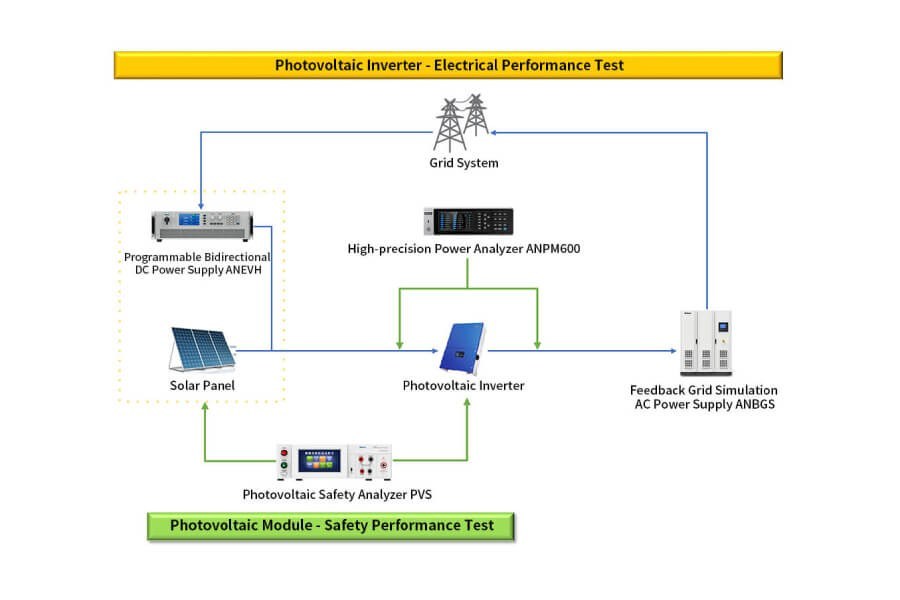
A test system can combine a DC power simulator, an AC load or grid simulator, a power analyzer, a data acquisition system, and automated control software. Together, these instruments simulate inputs and events while measuring electrical output and recording test data.
| Equipment | Role in the test system | Example identified in the source |
|---|---|---|
| DC power simulator | Simulates photovoltaic array I-V characteristics | ANEVH series |
| AC load/grid simulator | Reproduces grid fluctuations and fault scenarios | AN236 series |
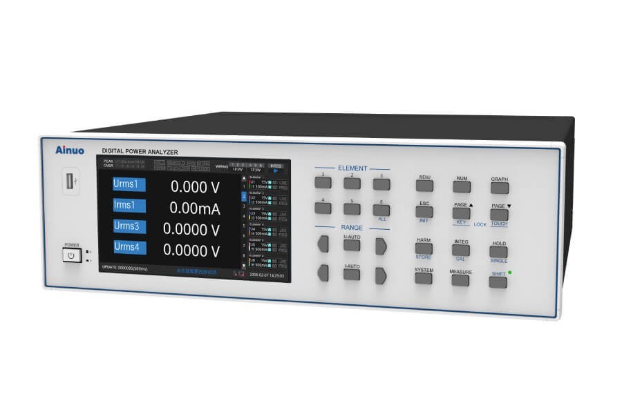
| Power analyzer | Measures input/output power and harmonics | ANPM600 series |
| Data acquisition system | Records values such as temperature and voltage | Not specified |
How should photovoltaic inverter test results be evaluated?
Test results should be reviewed as a combined picture of functional operation, efficiency and stability, protective response, power quality, and environmental behavior. The evaluation should compare recorded voltage, frequency, waveform, harmonics, alarms, disconnection behavior, and thermal data with the defined requirements for the test.
Automated test control can generate irradiance curves and grid-fault sequences, improving repeatability and producing standardized records. This makes it easier to assess how the inverter performs across normal operation, changing input conditions, and simulated fault events.