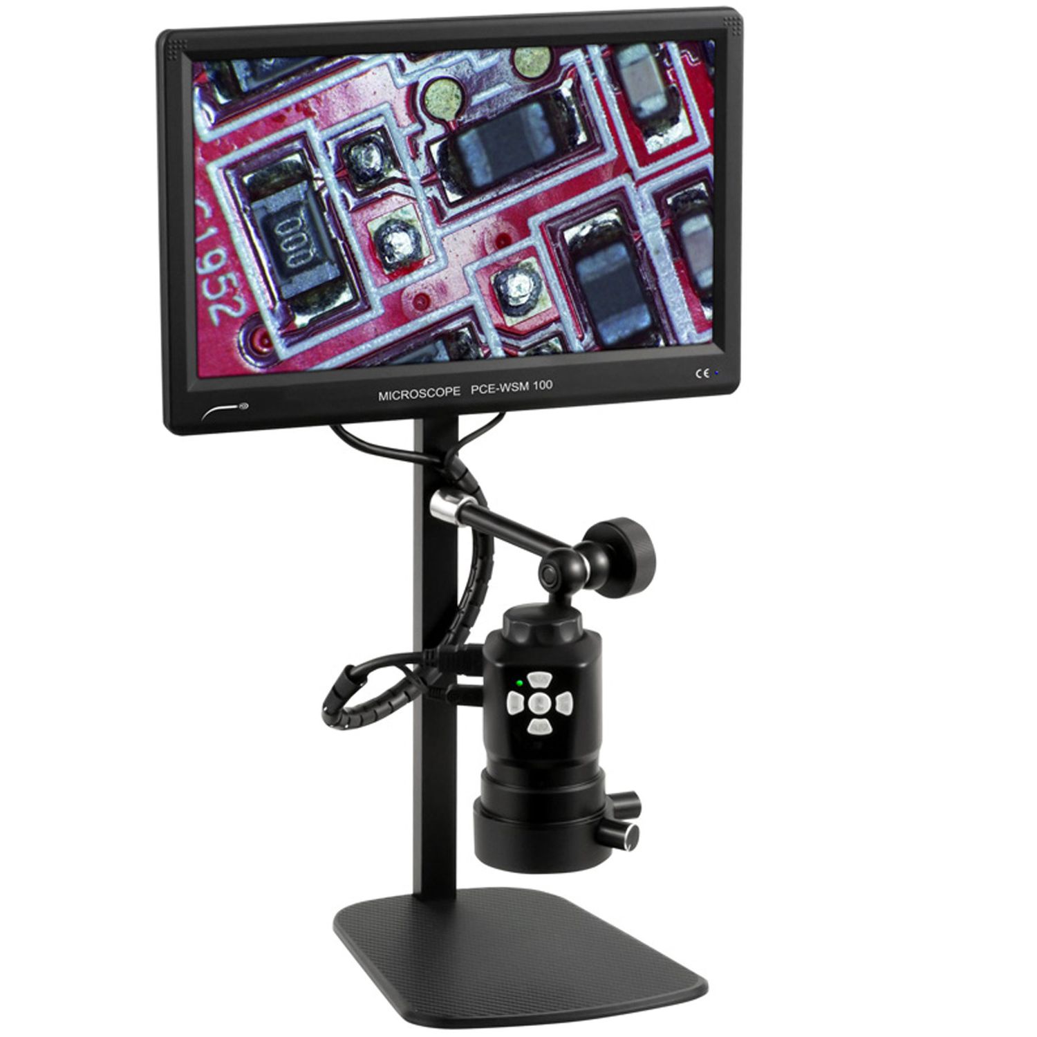
A microscope for electronic circuit inspection with a magnification range of approximately 5–30X can meet most inspection requirements, from general observation to inspecting solder joints and small components. For very small details, such as densely packed SMD components, magnification in the 20–45X range can be more useful. Magnification should be selected based on the specific details being inspected rather than the overall size of the PCB.
What Magnification Is Needed for PCB Inspection?
At 5–10X, users can observe a relatively large area of the PCB, inspect component positions, traces, larger solder joints, and identify visible defects. This magnification range is also useful for quickly locating areas that may require further inspection.
The 10–20X range is more suitable for inspecting solder joints, component leads, and common SMD components. This is often a practical magnification range because it provides sufficient detail while maintaining a field of view that is wide enough for hands-on work.
When inspecting small SMD components, closely spaced IC pins, or very small defects, 20–30X can provide more detailed images. For 0402 and 0201 components or applications requiring closer analysis, a magnification range of approximately 20–45X may be necessary.
A microscope with an adjustable magnification range allows technicians to quickly move from an overall view to a specific defect without changing equipment.
For PCB inspection, an effective configuration needs to balance magnification, field of view, working distance, and illumination.
Why Doesn't Higher Magnification Always Mean Better PCB Inspection?
A 40X microscope is not necessarily more effective than a 20X microscope for PCB inspection.
As magnification increases, the field of view becomes smaller. The user may clearly see a single component pin but have difficulty identifying its position within the surrounding PCB area. Locating defects and moving between components can also take more time.
This is particularly relevant to PCB inspection because operators constantly move through several stages: overall observation → locating the defect → detailed inspection at higher magnification → repair work. A continuous zoom system is therefore more convenient than a microscope with only one fixed magnification level.
Working Distance Is Just as Important as Magnification
When inspecting a PCB for repair, having a clear image is not enough. The operator's hands and tools must also have sufficient access to the area being worked on.
Working distance is the distance between the objective lens and the specimen surface when the image is in focus. An appropriate working distance provides more space for positioning tweezers, soldering irons, or inspection tools beneath the microscope.
Some stereo microscopes designed for electronics repair are available in configurations such as 10–20–30–40X or 20–40X, while also providing sufficient working space for soldering and precision mechanical work.
Lighting Can Determine Whether a Defect Is Visible
A solder joint may be clearly within the field of view but still be difficult to evaluate if the lighting and reflections are not appropriate.
PCB surfaces, component leads, and solder have different reflective properties. Changing the illumination angle can make cracks, solder bridges, insufficient solder, or excess material more visible—or make them harder to detect.
Optical microscopes used for PCB inspection often combine ring illumination with directional lighting. For defects on reflective surfaces, adjustable lighting can sometimes improve image visibility more effectively than increasing magnification from 20X to 40X.
This is also one reason stereo microscopes are widely used for PCB inspection: the stereoscopic optical system, combined with suitable illumination, supports both surface observation and direct manipulation of the circuit board.
=> See also: Should You Choose a Binocular or Trinocular Stereo Microscope?
Frequently Asked Questions (FAQ)
What Magnification Should a Microscope for PCB Inspection Have?
A magnification range of 10–20X is suitable for many common PCB inspection and repair tasks. For very small SMD components, 20–45X may be required.
Should You Use a 40X Microscope for PCB Repair?
It can be used, but magnification should not be the only consideration. Field of view, working distance, and adjustable magnification should also be evaluated.
Is a Stereo Microscope Suitable for PCB Repair?
Yes. Its stereoscopic image, working distance, and ability to support direct manipulation under the objective lens make a stereo microscope suitable for PCB inspection and repair.
What Specifications Should Be Considered Besides Magnification?
In addition to the magnification of the microscope, users should consider working distance, field of view, zoom range, optical resolution, and the illumination system. For quality control applications, camera connectivity and image documentation should also be taken into account.