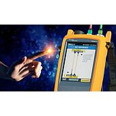
Fiber polarity is the signal path through a fiber link: the transmit side (Tx) at one end must connect to the receive side (Rx) at the other. In a duplex link, a Tx-to-Tx connection prevents data flow, even if the link includes multiple cable segments or patch-panel adapters.
For MPO-based duplex cabling, polarity is determined by the trunk, cassette transition, adapter type, and patch-cord arrangement. These components must be selected as one consistent method rather than mixed between schemes.
Summary: Duplex links require Tx-to-Rx continuity. A-B duplex patch cords provide straight-through polarity in end-to-end duplex channels. MPO Methods A, B, C, U1 and U2 use different component arrangements. U1 and U2 support transition to parallel optics, while U2 also supports direct breakout applications.
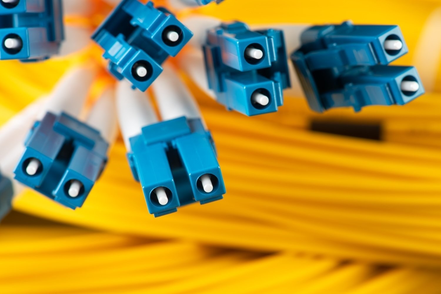
What is fiber polarity in a duplex fiber link?
Fiber polarity is the direction of the optical signal from one end of a link to the other. A duplex connection uses two fibers for bidirectional transmission, with each fiber carrying a path between a transmitter and a receiver.
The fundamental requirement is unchanged across the channel: Tx must connect to Rx. Connector keys help maintain the intended Tx/Rx position and prevent fiber rotation when connectors are mated.
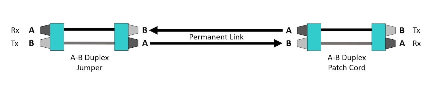
Which patch-cord polarity is used for end-to-end duplex connections?
An A-B polarity arrangement is recommended for duplex patch cords in an end-to-end channel. An A-B patch cord creates a straight-through connection that maintains the required A-B relationship from one end of the duplex channel to the other.
This principle applies regardless of the number of intervening adapters, patch panels, or cable sections. The active equipment still needs the Tx position at one end to reach the corresponding Rx position at the other.
Why is MPO-based duplex polarity more complex?
MPO-based duplex polarity is more complex because a multi-fiber trunk must transition its fiber positions into individual duplex connections. The outcome depends on the selected trunk type, cassette transition, adapter type, and patch cords.
Methods A, B, and C were originally defined for array-based duplex applications. The newer universal U1 and U2 methods use Type B trunks and A-B patch cords while keeping both cassettes in the same orientation.
How do MPO Methods A, B, C, U1, and U2 differ for duplex signals?
Each method establishes Tx-to-Rx continuity through a different combination of MPO trunk behavior and transition components. The practical differences include the type of patch cords needed, cassette orientation, and support for future application changes.
| Method | Trunk and connection approach | Duplex operational consideration |
|---|---|---|
| Method A | Type A straight-through MPO trunk; Type A transition and Type A adapters | Requires non-standard A-A duplex patch cords at one end to make the required flip. |
| Method B | Type B reversed MPO trunk; Type A transition and Type B adapters | Uses A-B patch cords at both equipment ends, but may require an inverted cassette or two cassette types. |
| Method C | Type C trunk with an internal pair flip; Type A transition and Type A adapters | Uses A-B patch cords at both ends, but does not readily support parallel 8-fiber applications. |
| Method U1 | Type B trunk; U1 transition and Type A adapters | Uses A-B patch cords at both ends and supports transition to parallel optics. |
| Method U2 | Type B trunk; U1 transition and Type B adapters | Uses A-B patch cords at both ends, supports parallel optics, and supports direct breakout applications. |
When should a polarity method support parallel optics or direct breakouts?
A method that supports parallel optics can simplify a future migration from duplex applications to parallel optical applications. Both U1 and U2 support transitioning to parallel optics.
Method U2 additionally supports direct breakout use cases, where one high-speed parallel-optic switch port connects to multiple lower-speed duplex ports. The provided example is an 8-fiber 400 Gig switch port connecting four duplex 100 Gig servers in a 4X100 arrangement.
Using U1 for direct breakout applications requires non-standard A-A duplex patch cords. Method C is not readily suited to parallel 8-fiber applications because of its internal pair flip.
What should be checked before selecting an MPO polarity scheme?
Select one compatible polarity method for the complete channel and keep it consistent. Components from different methods should not be mixed, because the methods are mutually incompatible.
Also assess operational handling, including whether different cassettes or patch cords are required at opposite ends and whether special labeling may be needed. Planning for a required migration path can reduce later component replacement and complexity.
Note: The key-up-to-key-up arrangement used in Method B is not suitable for MPO connectors with angled physical contact (APC) end faces, because the 8-degree angles cannot mate correctly.
How can duplex fiber polarity be checked safely?
Check polarity at the duplex ports where active equipment connects by determining which side of the port is active and confirming that it connects to the correct counterpart. This avoids relying on assumptions when both ends of a link cannot be viewed at once.
Never look directly into a fiber port to identify a transmitting fiber. The source guidance identifies this as potentially hazardous to the eyes and notes that the light cannot be seen directly.
Before connecting MPO trunks and cassettes in a duplex channel, inspect the MPO connectors and clean them if necessary. This complements polarity verification by addressing connector condition before the connection is made.
The FiberLert-125 fiber optic detector can be positioned in front of a fiber end or optical port to detect active fibers through visual and audible indicators. Once the active side has been identified, Tx–Rx connections can be made with less guesswork and a lower risk of incorrect connections.