Choosing Between Fans, Heatsinks, Thermal Pads, and Thermal Grease for High-Power Electronic Devices
SiC and GaN semiconductor components have high power densities and compact dimensions, concentrating heat within a very small chip area. The question of which cooling solution is most commonly used is often framed as a choice among four options: fans, heatsinks, thermal pads, and thermal grease. This framing needs some clarification because these four components occupy different positions along the same heat-transfer path. Most thermal designs combine several of them. This article explains the role of each component, how to select thermal interface materials, and how temperature affects measurement results.
What Are the Different Roles of Fans, Heatsinks, Thermal Pads, and Thermal Grease? Do You Need to Choose Only One?
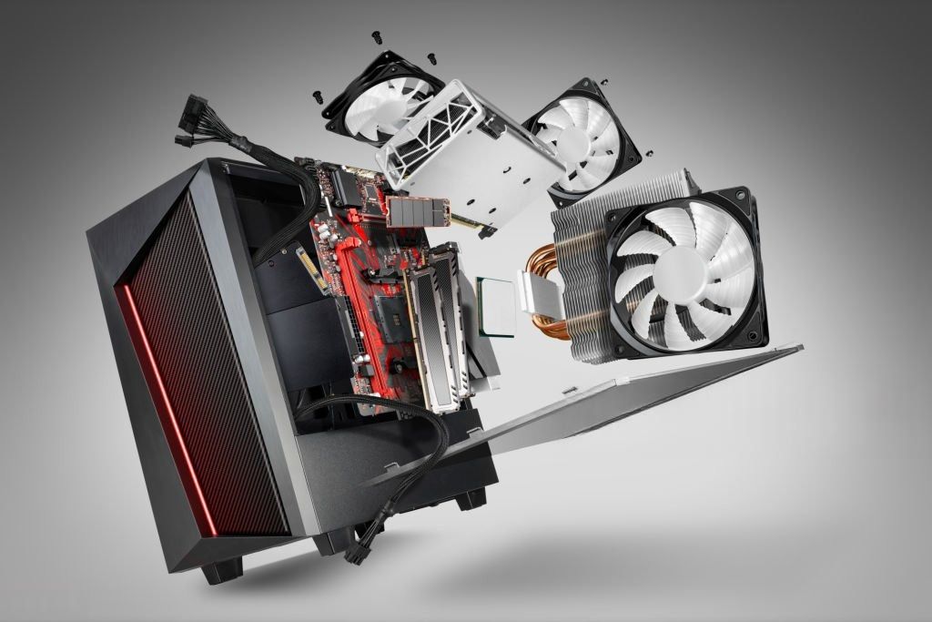
Heat travels from the chip through the component package, across the thermal interface material, into the heatsink, and finally dissipates into the surrounding air. Each component handles a different part of this process.
Provides a large surface area in contact with the air, receiving heat from the component and dissipating it into the surrounding environment.
Forces airflow through the heatsink, increasing the amount of heat carried away. It is used when natural cooling is insufficient.
These are thermal interface materials (TIMs) placed between the component and the heatsink. Even carefully machined metal surfaces contain microscopic gaps filled with air. Since air is a poor thermal conductor, with a thermal conductivity of approximately 0.026 W/m·K, TIMs fill these gaps with materials that conduct heat more effectively.
Therefore, thermal grease and thermal pads are two alternative solutions for the same interface position. Fans and heatsinks do not replace TIMs; they work alongside them.
How Does Total Thermal Resistance Determine Chip Temperature?
The junction temperature of a chip can be estimated using the thermal resistance network equation.
A technical document on thermal design for RF circuits provides an illustrative example: a contact interface without TIM can have a thermal resistance of approximately 2 to 20 °C/W, while using TIM can reduce it to approximately 0.05 to 1.0 °C/W.
Illustrative figures from a technical document. These are not universal values for all products.
These figures come from a specific technical document. Actual values depend on the material, surface flatness, and clamping force. The example shows that the interface layer can account for a significant portion of total thermal resistance, making TIM selection an essential design consideration rather than a secondary step.
When Should You Use Thermal Grease or Thermal Pads?
| Criteria | Thermal Grease | Thermal Pad |
|---|---|---|
| Interface layer thickness | Very thin when sufficient clamping force is applied | Thicker, depending on the pad thickness |
| Interface thermal resistance | Generally lower | Generally higher |
| Filling large gaps and uneven surfaces | Limited capability | Suitable; the soft pad compresses to conform to the surface |
| Components of different heights on the same PCB | Difficult to apply | Suitable; different thicknesses can be selected for each position |
| Long-term thermal cycling | May experience pump-out and gradual drying (dry-out) | Generally less susceptible to pump-out |
| Application and cleaning | Can spread easily and is difficult to apply uniformly | Clean and convenient; pre-cut pads provide better repeatability |
Pump-out occurs when the component and heatsink expand and contract at different rates during repeated heating and cooling cycles. This gradually pushes the grease layer from the center toward the edges, increasing the interface thickness and thermal resistance over time.
For thermal pads, select the thickness based on the worst-case gap after accounting for the tolerances of the components, PCB, heatsink, and mounting screws. Do not estimate the required thickness by eye. Avoid stacking multiple pads to compensate for gaps, as the interfaces between the pads introduce additional thermal resistance.
This material is solid at room temperature and softens when heated. It is less susceptible to pump-out than thermal grease but still requires sufficient clamping pressure.
How Should You Read Thermal Interface Material Specifications to Avoid Choosing the Wrong Product?
The thermal conductivity value (W/m·K) on the product label describes the bulk material. It does not fully represent the performance of the entire interface layer.
One supplier advises against replacing one material with another solely because its advertised W/m·K value is higher. More meaningful parameters for comparison include thermal resistance or thermal impedance at specified thicknesses and clamping pressures. The following points should be verified.
- Measurement method
- Thickness
- Tolerance
- Compression curve (for pads)
- Electrical insulation capability
- Operating temperature range
- Thermal cycling data
For thermal grease, the amount applied also has a significant impact. An excessively thick layer increases thermal resistance, while an excessively thin layer may be squeezed out of the interface.
Passive Heatsinks or Forced-Air Cooling: Which Is Suitable for Different Power Levels?
Very high power levels often require liquid-cooled cold plates, which are beyond the scope of this article.
These two points are general industry considerations. First, a heatsink connected to a switching node can introduce parasitic capacitance and potentially increase electromagnetic interference (EMI). Therefore, heatsink grounding should be carefully considered.
Second, the fan motor can introduce electrical noise into the power supply lines. Filtering may be necessary, or the fan power supply may need to be separated from sensitive measurement circuits.
How Does Temperature Affect Measurements on SiC and GaN Components, and How Can Measurement Errors Be Reduced?
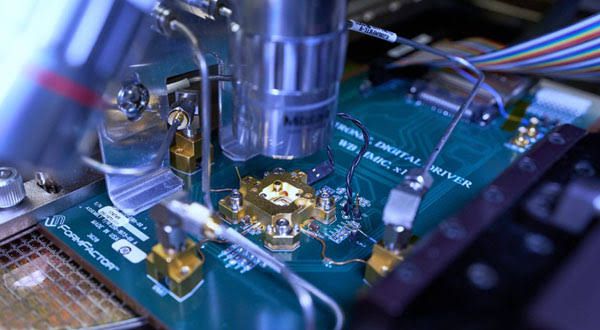
Tektronix notes that SiC and GaN devices offer high power density and compact dimensions, better high-temperature performance than silicon, higher operating frequencies, and lower on-resistance. However, their high power density also makes self-heating more pronounced. When a chip heats itself during measurement, the channel temperature rises and the measured current changes. As a result, the measurement reflects both the device characteristics and the level of self-heating. A study on GaN HEMTs shows that saturation current decreases as channel temperature increases, whether the temperature rise is caused by self-heating or external heating. Bare devices without adequate thermal management are particularly susceptible to this effect.
The following methods can help reduce measurement errors, based on technical literature on SiC and GaN testing.
A technical article on GaN and SiC testing states that measurement pulses shorter than 50 µs help prevent self-heating from affecting the accuracy of I-V characteristics. Pulsed current measurements also help control self-heating when measuring on-resistance.
Use the double-pulse test (DPT) to measure switching characteristics. This method is widely used for wide-bandgap semiconductor devices and can be performed using an arbitrary/function generator (AFG) together with an oscilloscope. Tektronix offers the WBG-DPT solution, which runs on the 5 Series MSO oscilloscope and automates switching measurements for GaN and SiC devices.
Record the case or heatsink temperature, allow the temperature to stabilize before measurement, and maintain consistent TIM conditions (type, thickness, and clamping force) between tests to ensure comparable results. This is a general recommendation and is not directly quoted from a manufacturer document.
Use pulsed measurements to distinguish the effects of self-heating from external heating, following approaches used in academic studies to determine channel thermal resistance.
What Are the Steps for Selecting a Thermal Management Solution for a High-Power PCB?
Determine the maximum power dissipation of each component, the ambient temperature, and the maximum allowable junction temperature.
Calculate the allowable total thermal resistance. Subtract the Rjc value specified by the chip manufacturer, then allocate the remaining thermal resistance to Rcs and Rsa.
Select a heatsink and airflow solution (natural convection or forced-air cooling) that meets the Rsa requirement.
Measure the actual gap between the component and heatsink. Select a TIM based on the gap, surface flatness, clamping pressure, electrical insulation requirements, and the number of thermal cycles.
Assemble a prototype and measure the temperature under actual operating power conditions. Compare the results with the calculations.
Recheck the system after several heating and cooling cycles, especially when using thermal grease, to identify potential pump-out.
Experience Hands-On SiC and GaN Device Testing at Tektronix Semiconductor Seminar 2026
Organized jointly by EMIN and Tektronix, the seminar features live demonstrations that allow participants to work directly with MSO Series oscilloscopes, Keithley SMUs, and next-generation AI power testing equipment alongside Tektronix experts. Seating is limited, so register early to secure your place with EMIN.
- Wednesday, November 11, 2026
- 9:00 AM – 2:00 PM
- 6th Floor, NIC Building, Hanoi
- Tea break and networking lunch included