Why Neutral Wires Were Traditionally Sized Smaller
In a balanced three-phase system with purely linear loads, the three phase currents are 120 degrees out of phase and cancel each other out at the neutral point, resulting in near-zero current returning through the neutral wire. Cable sizing formulas have historically relied on this assumption, leading engineers to select neutral conductors with a cross-sectional area equal to or smaller than phase conductors under the premise that they only carry minor imbalance currents.
The problem is that real-world loads rarely match this assumption anymore. Computer power supplies, variable frequency drives (VFDs), LED drivers, UPS systems, and power electronics are all non-linear loads. Rather than drawing purely sinusoidal current, they draw distorted current waveforms that generate high-order harmonics superimposed on the fundamental 50Hz frequency.
Triplen Harmonics Accumulate in the Neutral Conductor
Among the harmonic orders, triplen harmonics—specifically the 3rd, 9th, and 15th orders—behave fundamentally differently from other harmonic components. At the fundamental frequency, phase currents are displaced by 120 degrees and cancel out at the neutral as expected. However, for triplen harmonics, this phase displacement is multiplied threefold, causing the 3rd harmonic components across all three phases to become in-phase with one another rather than offset.
Being in-phase means they add up constructively instead of canceling out. The entire 3rd harmonic current from all three phases channels directly into the neutral wire. As a result, neutral current not only fails to reach zero but can actually exceed the RMS current of the individual phase wires—particularly in office buildings, data centers, and facilities with high densities of electronic equipment and LED lighting.
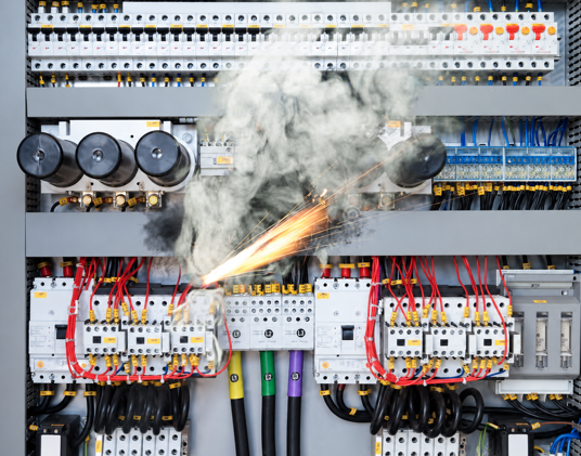
Neutral conductors originally sized smaller than phase conductors are forced to carry currents exceeding phase ratings, causing operating temperatures to spike beyond thermal insulation limits. Over time, neutral wire insulation degrades rapidly, becoming brittle and cracked, which significantly increases fire risks—especially at junctions and terminal blocks where contact resistance is inherently elevated.
Beyond fire hazards, excessive neutral harmonic currents induce voltage drops and waveform distortion at the point of common coupling, creating negative feedback that affects sensitive equipment across the entire network. Power transformers supplying non-linear loads suffer additional harmonic losses, running hotter than designed and shortening their operational lifespan over time.
Upgrading Wire Size Does Not Solve the Root Cause
When discovering an overheating neutral wire, many maintenance teams simply measure the current using a standard clamp meter, confirm the high reading, and swap in a larger conductor. This approach merely treats the symptom without addressing the root cause, leaving harmonic generation from non-linear loads active and free to disrupt other critical areas of the electrical system.
Accurately determining harmonic severity and origins requires specialized test equipment capable of individual harmonic order spectrum analysis rather than basic total RMS measurements. Power quality analyzers provide visibility into Total Harmonic Distortion (THD) for both voltage and current, map energy distribution across harmonic orders, and pinpoint dominant harmonics alongside their primary sources.
3 Critical Factors to Evaluate During Field Testing
When abnormal neutral currents point to potential harmonic issues, diagnostic testing must answer three key questions: What are the current Total Harmonic Distortion (THD-I) levels on each phase and the neutral relative to recommended thresholds? What proportion do 3rd and 9th order harmonics represent within the total measured spectrum? And most importantly, which specific loads in the facility are contributing the majority of this harmonic distortion?
Fluke Power Quality Analyzers simultaneously capture voltage and current waveforms across all four conductors, isolate individual harmonic orders, and log long-term telemetry to map against real-world load duty cycles, delivering comprehensive insights that single-point snapshot measurements cannot provide.

Remediation Strategies Once Causes Are Identified
Once harmonic sources are clearly identified, corrective engineering options include oversizing neutral conductors to safely handle actual harmonic loads rather than legacy standards, installing K-factor rated isolation transformers dedicated to concentrated non-linear loads, or adding harmonic filters at key generation points to mitigate distortion at the source before it propagates through the distribution system.
Selecting the optimal solution depends entirely on empirical measurement data; generic fixes should never be applied without first establishing the precise magnitude and nature of the issue. Targeted diagnostic investments yield significant long-term savings compared to trial-and-error modifications on live operational infrastructure.